Chapter 7 Explanation of Functions
7 - 23
(2) Automatic torque boost
When automatic torque boost (data "01") is selected by the torque boost selection (A041/A241), the
inverter automatically adjusts the output frequency and voltage according to the load on the motor.
(During actual operation, the automatic torque boost is usually combined with the manual torque boost.)
When you select the automatic torque boost, adjust the settings of the motor capacity selection
(H003/H203) and motor pole selection (H004/H204) according to the motor to be driven.
If the inverter trips due to overcurrent during motor deceleration, set the AVR function select (A081) to
always enable the AVR function (data "00").
If you cannot obtain the desired operation characteristic by using the automatic torque boost, make the
following adjustments:
Symptom Adjustment method Adjustment item
Motor torque is insufficient at low
speed.
(The motor does not rotate at low
speed.)
(1) Increase the voltage setting for manual torque boost
step by step.
A042/A242
(2) Increase the slippage compensation gain for
automatic torque boost step by step.
A047/A247
(3) Increase the voltage compensation gain for
automatic torque boost step by step.
A046/A246
(4) Reduce the carrier frequency setting. b083
The motor speed falls when a load
is applied to the motor.
Increase the slippage compensation gain for the
automatic torque boost step by step.
A047/A247
The motor speed increases when a
load is applied to the motor.
Reduce the slippage compensation gain for the
automatic torque boost step by step.
A047/A247
The inverter trips due to overcurrent
when a load is applied to the motor.
(1) Reduce the voltage compensation gain for the
automatic torque boost step by step.
A046/A246
(2) Reduce the slippage compensation gain for the
automatic torque boost step by step.
A047/A247
(3) Reduce the voltage setting for the manual torque
boost step by step.
A042/A242
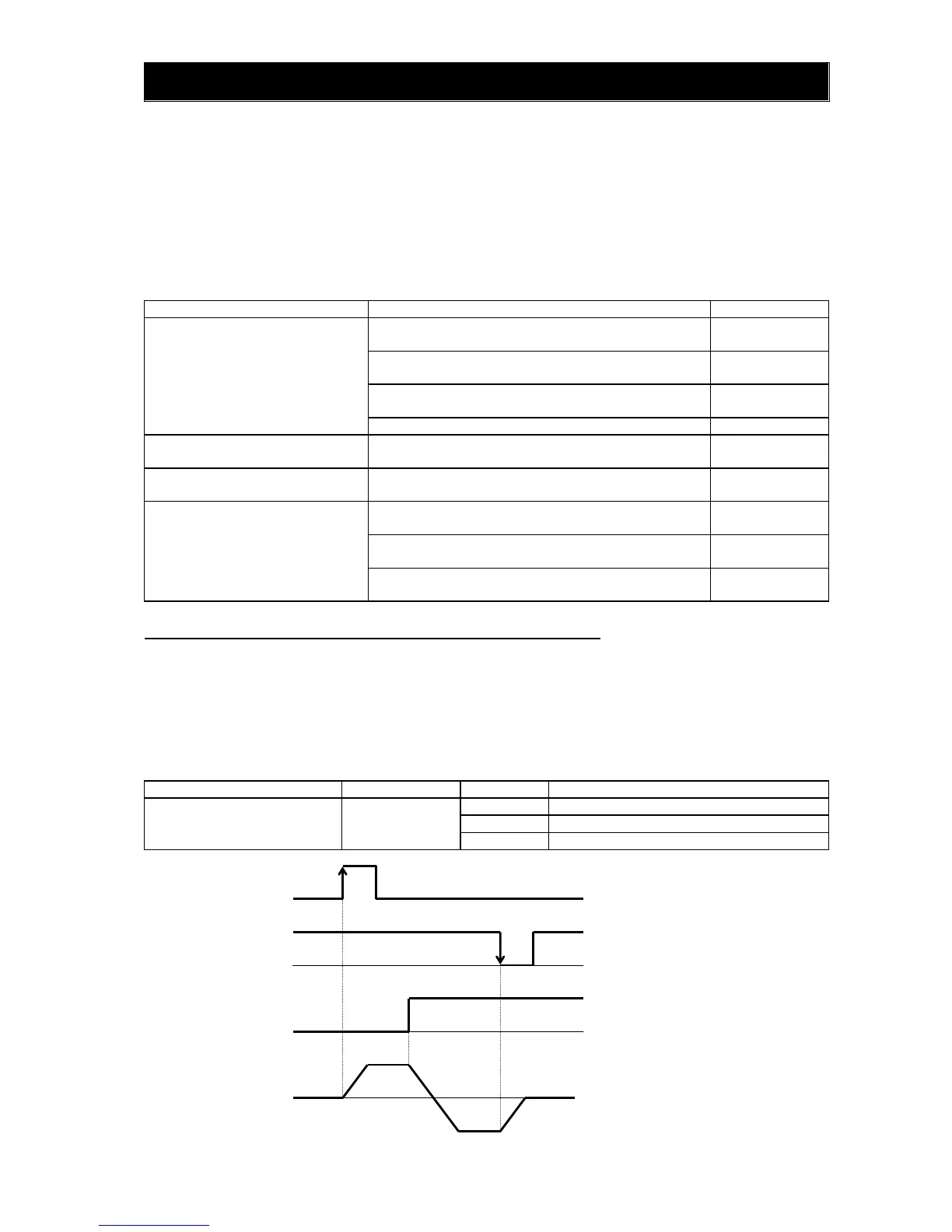
7.5.3 3-wire interface operation function (STA, STP, and F/R)
The 3-wire interface operation function allows you to use automatic- reset contacts (e.g., pushbutton
switches) to start and stop the inverter.
Specify "01" (control circuit terminal block) for the run command source setting (A002).
Assign function "20" (STA), "21" (STP), and "22" (F/R) to three of the terminal [1] to [5] functions (C001 to
C005) to enable the control operations described below. Assigning the STP function to an intelligent input
terminal disables the functions of the FW and RV terminals.
While the (STP) is OFF , the (STA) is invalid.
Item Function code Data Description
Terminal [1] to [5] functions C001 to C005
20 STA: Starting the motor
21 STP: Stopping the motor
22 F/R: Switching the motor operation direction
Output frequency
OFF
OFF
ON
ON
F/R
STP
STA
Forward
rotation
Reverse
rotation
Note : In 3 wire input , STP input is
used at the b point of contact.
But the setting of STP is the a
 Loading...