Check the contents and the quantity of the accessories in the packing.
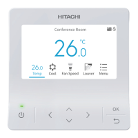
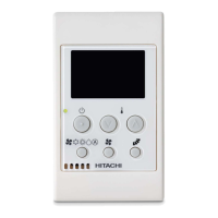
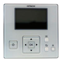
(ii)A-Remotecontrolswitchforoperationcontrol
B-2M4x16Lscrewsforxationoftheholdingbracketontothewallorunit
C-1InstructionManual
In case of installing multiple controllers in a vertical arrangement, a clearance of more than
50 mm shall be kept between controllers (iii).
2.1 INSTALLATION PROCEDURE
1 Insert the tip of a slotted screwdriver into the notches at the bottom of the holding
bracket, push and turn the slotted screw driver and then remove the holding bracket from
the remote control switch.
(iv)A-Notches
B-Approx.6mm
C-Slottedscrewdriver
D-Viewfromthebottomside
E-Rearcover
F-Notchforattachmentofthecontroller
2 Attach the remote control switch to the holding bracket and connect the cable as follows:
- In case of direct connection of exposed remote control cable.
Fix the holding bracket onto the wall with screws (accessory). (v)
Attach the stopper (plastic band) to the cable at the inner side of the draw-out hole.
(vi)B-Cable
C-Bandstopper(Field-supplied)
D-Draw-outhole
E-Leadthecablewithitssheathpeeledthroughthe
groove
F-Peeltheinsulationattheendofthecableand
clamptheM3solderlessterminals(eld-supplied)
- When using a switch box
i. Prepare a eld-supplied implanted switch box (JIS C 8336-1988 type)
ii. Lead the cable through the conduit tube in the wall.
(vii)G-Implantedswitchbox(JISBox)with4xingtabs
H-Implantedswitchbox(JISBox)with2xingtabs
I-M4screws(eld-supplied)
iii. Peel the insulation at the end of the cable and clamp the M3 solderless terminals
(eld-supplied). Connecttheterminals(J)
3 Attach the remote control switch to the holding bracket. Be careful not to pinch the cable
when attaching it.
4 Remove the protection lm from the liquid crystal display. (viii)
Installation
PMML0519 rev.0 - 03/2019
2
 Loading...