16.2 IN ABNORMAL CONDITION
16.2.1 Abnormality
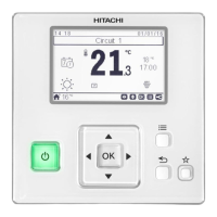
The RUN indicator (Red) is ashing.
The indoor unit number, the alarm code, the model code, *model
name (Ex. RCI-3.0FSN3) and the connected number of indoor
units are displayed on LCD.
(*The unit model name is only displayed for the corresponding
unit model.)
In case that the plural indoor units are connected, the above
items for each indoor unit are displayed one by one.
16.2.2 Power failure
All the indications are OFF.
Once the unit is stopped by the power failure, the unit will not be
started again although the power recovers. Perform the starting
procedures again.
In case of instantaneous power failure within 2 seconds, the unit
will be started again automatically.
16.2.3 Electric noise
There could be a case that all the indications are OFF and the
unit is stopped. This is occurred by the activation of the micro
computer for the unit protection from the electric noise.
Perform the starting procedures again.
16.3 ALARM CODES
Code
number
Category Abnormality Cause
01 Indoor unit Activation of the safety device Failure of fan motor, drain discharge, PCB, relay, oat switch activated
02 Outdoor unit Activation of the safety device Failure of fan motor, drain discharge, PCB, relay, oat switch activated
03
Transmission
Abnormal transmission between
outdoor and indoor units
Incorrect wiring, failure of PCB, tripping of fuse, power supply OFF
04
Abnormal transmission between
inverter PCB (DIP-IPM) and outdoor
unit PCB (PCB1)
Abnormal transmission between PCB
04.
Abnormal transmission between fan
controller and outdoor PCB
Fan controller - Outdoor PCB transmission fault (loose connector, broken
cable, blown fuse)
05 Power supply
Abnormal operation of picking up phase
signal
Main power supply phase is reversely connected or one phase is not
connected
06
Voltage
Excessively low voltage or excessively
high voltage for the inverter
Incorrect wiring or insucient capacity of power supply wiring
06. Abnormal fan controller voltage Outdoor voltage drop, insucient power
07
Cycle
Decrease in discharge gas superheat Discharge gas superheat less than 10 degrees is maintained for 30 minutes.
08
Excessively high discharge gas
temperature at the top of compressor
Temperature of top compressor: Td
Td > 132°C over 10 minutes, or Td >140°C over 5 minutes
09 Fan motor
Activation of protection device for
outdoor fan
Fan motor overheat, locking
0A Transmission
Abnormal transmission between
outdoor and indoor unit
Incorrect wiring, broken cable, loose terminals
0b
Outdoor unit
Incorrect outdoor unit address setting
Duplicate address setting of outdoor units (secondary units) in the same
refrigerant system
0C
Main unit of the outdoor unit incorrectly
set
Two or more outdoor units dened as the “main unit” in the same refrigerant
cycle system
OTHER INDICATIONS
PMML0404A rev.1.1 - 06/2022
40
 Loading...