(*1): Do not set “STOP” or “Run Mode Shift” when using other central stations at the same time. When setting outdoor
unit capacity control, set one of the central station and do not set the others.
(*2): Setting is only possible for Stop or Run Mode Shift. And it is not possible to set multiple contact points.
(*3): When operating in “AUTO” mode, or when “Fixing Operation Mode” is enabled at “Optional Function Setting”.
(*4): Operation stops even if it is in Auto mode, or if the operation mode is xed in the optional function settings.
(*5): Outdoor unit capacity control can be set to multiple contact points. When there is a signal input in multiple contact
points, the priority for the execution of the controls is established according to the input number (Input 1 > Input 2 >
Input 3 > Input 4).
(*6): There are cases in which the outdoor unit may not support certain settings, or in which available settings may dif-
fer according to its capacity value. Please contact with your dealer or with the designated customer service centre for
detailed information.
(*7): It is possible to control via schedule without using demand control.
External Output Function
1 All Run Output
External output of indoor unit operation signal to the target group. The operation signal is output even if one indoor unit in
the target group is in operation.
2 External Output Alarm
External output alarm signal of indoor units to the target group. The alarm signal is output even if one indoor unit abnor-
mality occurs in the target group.
Specications of the External Input/Output Terminals
• Input Terminal: Non-voltage contact (normal open) for demand signal Input DC12V, 10 mA
The contact can be switched.
Pulse width is 300 ms or more for pulse signal input.
• Output Terminal: Contact (voltage is applied) for signal Output DC12V
Recommended Relay: MY Relay manufactured by Omron Corporation
(Do not use a diode built-in type.)
• Input/Output connection: using accessory connector cord
Connection procedure:
1
In case that there is a section of cord which is not going
to be used, please conrm the connector number, cut
the cord as shown in the gure on the right, and protect
the cut section with locally supplied insulation tape.
Cut out this portion.
Protect the cut part using insulation tape.
Insulation tape
Cut part
2
Follow one of the procedures below in order to connect
a relay or a timer with a locally supplied cord.
a.
Soldering
Twist and solder copper wires together and insulate
them by winding plastic tape around.
b.
Caulking with closed-end connector accessory
Insert the closed-end connector after twisting and
soldering copper wires together, then caulk with a
clamping tool.(pull the cord to check the tightness of
the connection)
Close-end
Connector
Cord (eld-supplied)
Copper wires
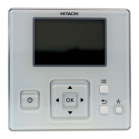
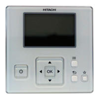
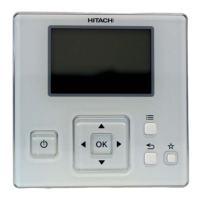
5 Centralised remote controls
PSC-A32MN
TCGB0106 rev.0 - 12/2014
356

 Loading...