CN4
CN9
CN1
CN5
CN11
CN10
Elec-cov-u
Elec-cov-s
IndicatingP.W.B.
Elec-cov-upper
Elec-cov-Lower
Wirecolorofwhite
Wirecolorofblack
Screwforfixelec-cov-s
Thepawlofelec-cov-ushallbehookedon
thecuttingportionofelec-cov-s.
Thentheelec-cov-ushallbeinserted.
A B C D
Thelowerprojectionofelectricalpartsshallbesuretobehookedincabinet.
Wheninstallingtheparts,usecautionnottopinchanycodebetweenthe
partandcabinet.
Screwforfixwireofearth
Screwforfixelectricalparts
MODEL RAS-10JH4, RAS-14JH4
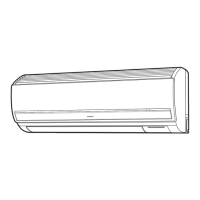
STRUCTURE OF AN INDOOR UNIT ELECTRIC PARTS
CN7
CN3
CN8
CN2
IndicatingP.W.B.(atswitch)
IndicatingP.W.B.(atdisplaypanel)
Switchcover
PawlstofixP.W.B.(2places)
PawlstofixP.W.B.(5places)
PawlstofixP.W.B.(4places)
1. Removing elec-cov-u. However, be cautious as indicating P.W.B. is attached to the cover.
2. Remove the connectors of CN1 (Thermistor), CN4 (Stepping motor for auto sweep), CN5 (Ventilation damper motor),
CN9 (Gas sensor), CN10 (Indoor fan motor) and CN11 (Ventilation fan motor) from control P.W.B.
3. Remove the fixing screw for electric part (2 places) and earth wire then remove the electric parts.
In case the connector cannot be removed in the step2. above, remove the securing screws for electric part cover S, CN3,
CN7 connecters and black and white wire of terminal A,B and then remove the electric part cover.
※
Removing electrical parts
1. Remove the securing screws for electric part cover S, CN3, CN7 connecters and black and white wire of terminal A,B and
then remove the electric part cover S.
2. Remove the CN2, Cn8 connecters from the control P.W.B.
3. Remove the upper part of securing pawls (2 places) and then remove the board.
HOW TO REMOVE CONTROL P.W.B.
1. Remove CN2 connecters from the control P.W.B. (or indicating P.W.B.).
2. Remove the upper part of securing pawls (2 places) and then remove the board.
HOW TO REMOVE INDICATING P.W.B. (at display panel)
1. Remove CN8 connecters from the control P.W.B. (or indicating P.W.B.).
2. Remove the right side of securing pawls and then remove the board.
HOW TO REMOVE INDICATING P.W.B. (at switch)
- 74 -

 Loading...