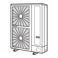
4 To remove the propeller fan, remove the cap nut and washer which fix the propeller fan onto the motor shaft. (Use a
puller when the propeller fan and motor shaft are fixed too tightly).
1. Upper cover.
1. Fan motor lead wire.
2. Motor clamp.
3. Motor.
4. Screw with spacer.
5 Remove the fan motor connector inserted into the electrical box DIP-IPM.
Cut the plastic tie with nippers, which fixes the fan motor lead wire onto the motor clamp.
Remove four (4) screws which fix the motor.
Model
RAS-4HVRNS1E RAS-5/6HVRNS1E
Connector pin location DIP-IPM - CN202
Motor fixing screws 4x M4 screws 4x M6 screws (with spacer)
1. Motor clamp.
2. Plastic tie.
3. Motor.
4. Wire.
N O T E
1 To mount the motor, be sure to place the lead wire outlet downward.
(Adjust the propeller fan and shroud not to contact with each other).
2 Fix the motor lead wire onto the motor clamp using a plastic tie as shown in the table on the previous page, to
avoid obstructing the propeller fan.
3 Mounting propeller fan:
Insert the skidding protection part of the fan boss matching with the motor shaft notch; tighten the nut after
the shaft screw fully comes out. (Tightening Torque 20 Nm)
4 Connect the motor lead wire to the electrical box DIP-IPM.
(Be sure to match colors of the PCB connectors and motor lead wire connectors).
5 Be sure to attach the outlet grill onto the shroud after replacing the fan motor.
¿ Removing electrical box
1 Remove the service cover following Removing service cover, see on page 402.
2 Remove the upper cover following Removing upper cover, see on page 403.
10 Servicing
405
SMGB0060 rev. 1- 12/2010
10

 Loading...


