– 93 –
R297
R298
C208
R108
R107
C101
VSD
RC Filter
Motor coil
System power module
Power supply for DC fan motor from smoothing
capacitor in system power module
roticapaCgnihtoomS
U
V
W
BOARD
DC Fan motor with control board
CIREVIRDPIHCENO
R242
HIC
0V
0V
0V
0V
R283
R246
Q201
5V
PQ102
5V
5V
t
33.3KHz
Ap 7V
T/2
14
23
T
0V
0V
Vcc
PWM control voltage
FG Pulse
CN6
FM-0V
FM-15V
D101
Q101
R101
R102
Main P.W.B
CN12
FM-15V
FM-0V
12V
0V
0V
IC4
R244
Microcomputer
342R
501D
401R
501R
301R
601R
401
C
912C
411R
9
0
2
C
FM60 el
FG Pulse
input
Fig. 11-1
1
3
60
61
59
2
8
15
75
65
+
+
601C
301C
101DZ
+
511R
7
6
5
4
3
2
1
321
123 4 5321
+++
2A-FUSE
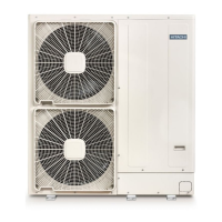
11. Outdoor DC Fan Motor control circuit.
●
This model uses DC Fan Motor which has a controller circuit in the Motor.
●
This DC Fan Motor will rotate by control voltage apply to Vsp input. (Voltage range: 1.7 to 7V DC)
Vsp high : Faster ; Vsp low : slower ; Vsp lower than 1.7V : stop
●
Motor will output FG pulse by following this motor revolution.
●
Outdoor Microprocessor will output PWM control signal from FMCHOP terminal by following the instruction
from indoor Microprocessor.
●
This PWM control signal will convert to Vsp voltage by smoothing circuit (Q101 & RC filter)
●
Fan motor will start to rotate when Vsp was proceeding over than 1.7V, and generate FG pulse by rotation
speed.
●
FG pulse will feed back to Outdoor Microprocessor through PQ102.
●
PQ102 is the isolator between Microprocessor circuit and DC Fan Motor circuit, which has to match the Fan
Motor revolution with instructed revolution. Such as...
FG feedback: Faster Ð Instruction: Slower ... Decrease pulse width
FG feedback: Slower Ð Instruction: Faster ... Increase pulse width
●
FG pulse is also used for Fan Motor failure detection
●
Microprocessor will monitor FG pulse 30 seconds after start the fan motor. If there is no signal detected, it
will consider that the Fan Motor was malfunction and stop the operation. In this case, LD302 on control PWB
will blink 12 times. (Fan Motor lock detected)
●
R107 and IC4 are used for Fan Motor over current
 Loading...