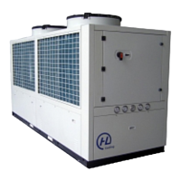
This document is a Use and Maintenance Handbook for HL-i Series Air Cooled Water Chillers with Axial Fans, manufactured by HL (Europe) Ltd. These units are designed for professional use and are available in cooling capacities ranging from 3KW to 180KW. The manual emphasizes compliance with CE certification and states that it is an essential part of every HL Cooling unit.
Function Description:
The HL-i Series chillers are air-cooled water chillers designed to provide cooling for various applications. They are equipped with a control microprocessor for managing operations, including fault and malfunction detection, ensuring safety for machinery, personnel, and the environment. The units are enclosed by panels to prevent access to dangerous areas, and fans are fitted with protection grilles. The chillers maintain an optimum water temperature to minimize compressor starts, contributing to a longer compressor life.
Important Technical Specifications:
- Cooling Capacities: 3KW to 180KW.
- Ambient Temperature Range: -10°C to 43°C.
- Water Temperature Range: -5°C to 35°C (LP Switch adjustment required if below 0°C).
- Minimum Outlet Evaporator Temperature: 5°C (excluding "brine" versions).
- Maximum Inlet Evaporator Temperature: 30°C.
- Water Flow Rate: Related to a 5°C temperature jump between input and output. Maximum allowable flow rate entails a 3°C jump; minimum allowable flow rate entails a 7°C jump.
- Water-Ethyl Glycol Mixture: Recommended for cool water temperatures below 4°C (out of the evaporator). A table is provided for freezing temperatures at various glycol percentages (5% to 40%).
- External Air Temperature for Cooling: -15°C to 40°C.
- Components: Control microprocessor, water fill & vent tank, special coated condenser fins, integral stainless steel tank, adjustable LP switch, centrifugal pump (standard 3 bar, optional 5 bar), heavy-duty condenser fan, and reliable compressor.
- Compressor: Highly reliable with high-efficiency performance, protected by an internal thermal overload.
- Condenser Fins: Aluminium fins coated with special anti-corrosion material for endurance.
- Water Tank: High volume integral stainless steel tank.
- Axial Fans: Directly coupled to an electric 8-6 pole motor with overload protection, electronic balancing, low-sound-level wing contour blades, and special air conveyor and protection grilles.
Usage Features:
- Installation: Units can be installed both indoors and outdoors. Considerations for positioning include hydraulic line length, power supply origin, free airflow, easy service access, and a strong, even surface.
- Hydraulic Connections: Inlet and outlet connections are not interchangeable. Suggestions for connecting to the application system include using vibration-damping joints, applying shutoff valves, and a by-pass valve. Thorough draining and air removal from the water circuit are crucial.
- Electrical Connections: Power supply must match nameplate data. Power supply cable section should not be smaller than indicated in wiring diagrams, and length should be moderate to avoid excessive voltage drops. Upstream cable protection (automatic circuit breaker or three fuses) is required, with breaking power at least equal to the maximum short-circuit current.
- CAREL Controller: The unit is managed by a CAREL µC²SE controller, which is the same size as a normal thermostat. It controls chillers and heat pumps, including air-air, air-water, water-water, and condensing units. A separate user manual for the controller is provided.
- Controller Display: Features a 3-digit display, showing decimal points between -99.9 and 99.9. In normal operation, it displays the temperature read by probe B1 (evaporator water inlet temperature or ambient air temperature).
- Parameter Access: Parameters are divided into 4 types based on user access level (password-protected).
- Start-up Procedure: Involves turning the main switch SW0 to "ON" and pressing a specific button on the controller for 5 seconds, followed by a 3-minute wait.
- Standby Procedure: Pressing a specific button on the controller for 5 seconds.
- Shut Down Procedure: Pressing a specific button on the controller for 5 seconds, then turning the main switch SW0 to "OFF".
- Changing Set Points: Instructions are provided for changing the water outlet cooling set point (r01), different set point (r02), and antifreeze alarm set point (A01) using the controller's "sel" and "Prg" buttons.
Maintenance Features:
- General Safety: All operations must be carried out by skilled personnel. Before any internal operation, the main power safety switch and the unit's main switch SW0 must be turned OFF. Operations with power supplied and panels open are only for trained technicians.
- Periodical Maintenance (Monthly):
- Check electrical terminals for correct clamping.
- Check remote control switch contacts for cleanliness and sound conditions (replace if necessary).
- Check water circuit for uniform filling (no air).
- Check water differential pressure switch operation.
- Clean condenser coil fins by blowing compressed air or flushing with water (opposite to airflow).
- Check defrost procedure performance.
- Extraordinary Checks: If anomalous noises occur after a few working hours, an extraordinary check is required.
- Cooling Circuit Maintenance:
- Refrigerant Exhaustion: During operations requiring cooling circuit exhaustion, gas must be collected into a proper receiver for environmental safety.
- Tightness Test: Fill the circuit with gaseous R407C to 1 bar, then add nitrogen to 15 bar. Check for leaks with a leak detector. Exhaust the circuit before welding if leaks are found. Emphasizes never using oxygen as a substitute for nitrogen.
- Draining and Drying: Use a suitable vacuum pump (1.4 mbar absolute pressure, 30 l/min. capacity). A three-fold pumping method is recommended if the circuit remains open for a long time or if moisture is present.
- Refrigerant Charge: Connect the refrigerant bomb to the 1/4" SAE male intake on the liquid line, blow out gas to exhaust air, then fill 75% of the total charge with liquid refrigerant. Connect to the suction line and fill completely with the bomb upright until the liquid tube temperature before the filter is 7-8°C lower than the R407C pressure gauge reading.
- Dismantling: When dismantling, drain the cooling circuit and collect gas in a suitable receiver. Compressor oil must be poured into a suitable receiver and sent to a specialized center for disposal. Improper disposal of gas or oil is strictly prohibited.
- Troubleshooting Guide: A comprehensive table of probable causes and possible cures for various issues, including the unit not starting, compressor not starting, compressor starting and stopping repeatedly, max/min pressure switch actuation, fans not starting, unit working but never stopping, pump not starting, and signal of water differential pressure switch not present.
- Alarm Error Code: A table listing alarm display codes, alarm types, resetting conditions, affected components (compressor, pump, fan, heater, valve), and descriptions, including warnings and advice. The manual notes that warning relays differ from alarm relays as they only activate for non-operational-affecting signals and do not show the alarm symbol.