SPECIFICATIONS
Frequently Asked Questions (FAQs)
1. What should the TDS readings be?
For drinking water and filter performance, the lower the TDS level, the better. There is never a
“right” or “wrong” number. For filter performance, calculate the percent rejection to determine
performance levels. Contact the manufacturer of your filter system for recommended levels.
2. My TDS levels fluctuate. Is this normal?
Yes. Slight fluctuations are normal from day-to-day. A variety of factors affect the reading.
3. Does the DM-1 have an alarm or programmable set point?
No. You will need to view the readings. Models QC-1, FM-1, FM-2 and others have alarms.
4. How will I know when the batteries need to be replaced?
If the display fades, the monitor does not power on, or the readings are incorrect, you may need
to change the batteries.
5. Can I use the DM-1 to monitor a water softener?
No. Water softeners do not remove TDS. Models FM-1 or FM-2 are suggested for softeners.
6. Where can I get more information on water quality?
Visit www.hmdigital.com
INSTRUCTIONS
To install the DM-1 to a water purification or filtration system:
1. Insert the white sensors fully into the bottom of the T-fittings.
2. Orient the sensor pins so that they are perpendicular to the direction of the T. The water
should flow over both pins equally. (You should be able to see both pins of you look
through the fitting.) See illustration #1 below.
3. Disconnect the water source.
4. Snip the source (tap) water tube at a point between the source and the filter. Insert both
ends of the tube into the top of the IN line sensor’s T-fitting. See illustration #2.
5. Snip the product (filtered) water tube at a point between the filter and a dispenser. Insert
both ends of the tube into the top of the OUT line sensor’s T-fitting. See illustration #2.
6. The DM-1 monitor can be attached anywhere on or near the water system using the Velcro
tape. Most commonly, the monitor is attached to the water filter system.
7. Reconnect the water source. Your monitor is now ready for use.
NOTE: Consult a professional plumber for specific installation questions.
Installation
TDS Range: 0-9990 ppm
Resolution: 0-999: 1 ppm
1000-9990: 10 ppm (indicated by a blinking ‘x10’ icon)
Accuracy: +/-2%
Conversion Factor: NaCl (avg. of 0.5)
Factory Calibration: 342 ppm NaCl
Sensor Cable Length: 24.5” (62.2 cm) (including sensor)
Power Source: 2 x 1.5V batteries (model 357A)
Auto Shut-Off: After 10 minutes
Battery Life: Approximately 2 years
Base Unit Dimensions: 3 x 0.8 x 1.9 in (7.6 x 2 x 4.7 cm)
Base Unit Weight: 2.8 oz (79.4 g) (including batteries)
CARE AND MAINTENANCE
Very little care is necessary for your DM-1
Never touch the sensor pins, as skin oils may adversely affect the TDS measurement.
To clean the sensor pins, clean with rubbing alcohol and let air dry.
Avoid removing the fittings, as doing this often may strip the plastic off the sensor and potentially
cause a leak.
If you notice the readings are off from what they should be, replace the batteries or re-calibrate.
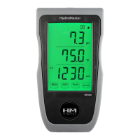
000
PPM
x10
Screen Description
TDS Level
Parts per million (equivalent to mg/L)
Times 10 indicator
(appears if over 999 ppm)
The DM-1 can be configured in a variety of ways, depending upon your needs.
Typically, the IN line (line 1) is connected to the source (tap) water, and the OUT line
(line 2) is connected to the product (filtered) water. The DM-1 can also be configured
with multiple systems, such as an RO/DI combination, as well as with HM Digital’s
Single Inline TDS Monitor (model SM-1).
Calibration
1. Purchase a certified calibration solution that is correct for your needs. The calibration solution
should be NaCl. HM Digital’s 342 ppm NaCl is recommended.
2. Disconnect both T-fittings from their tubes. Do not remove the sensor from the T! Ensure the
orientation of the sensor to the fitting is correct, as in illustration #1. Shake any water out.
3. For better accuracy, calibrate to a flowing solution. If this is not possible, you can calibrate to a still
solution. Turn on the monitor and place one T-fitting (with the sensors in it) into the calibration
solution. You will get a reading. Ensure the fitting is completely filled with solution and there are
no air bubbles. This step is critical for proper calibration.
4. If the reading on the monitor (for the sensor in the solution) does not match the solution, adjust the
reading up or down by gently turning the plastic orange screw on the rear of the unit clockwise or
counterclockwise to raise or lower the reading.
5. There is one calibration screw to calibrate both the IN and OUT sensors simultaneously. You only
need to calibrate one sensor, and it does not matter which.
6. If calibrating to a still (not flowing) solution, calibrate to 3% above the level of the calibration
solution. This will accomodate for the lack of flowing water, which the monitor is programmed for.
For example, if the calibration solution is 342 ppm, adjust the screws until it reads 352 ppm. If you
are calibrating to a flowing solution, calibrate to the level of the solution.
7. Your monitor is now calibrated. There is no need to do anything else.
Your monitor was factory calibrated to 342 ppm. This level is suitable for most tap water/filtered
water applications, so it is ready to use out of the box. However, you may need to re-calibrate based
on your needs, as well as from time-to-time to ensure best results. To calibrate:
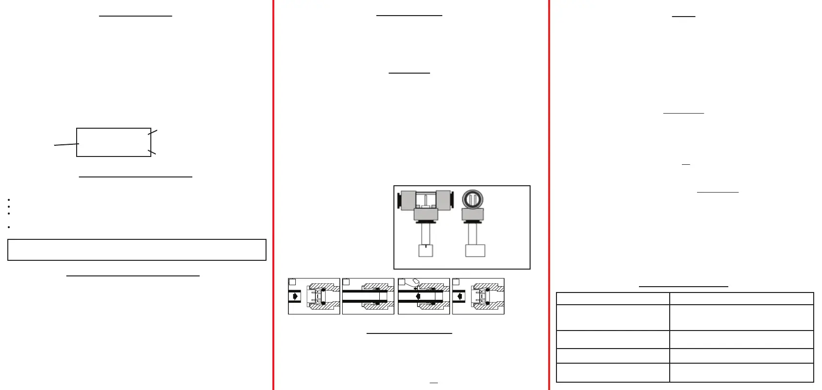
Avoid removing the ttings from the sensors. Excessive removal and insertion of the
ttings could ultimately scratch the sensor and potentially cause leakage.
1
12 2
Push tubing straight in as far as it can go. To remove, push in small collet and pull the tubing out.
LOOKING
THROUGH
THE
FITTING
SIDE VIEW
Illustration #1
To insert the sensor
into the fitting.
Illustration #2
To insert the tubing
into the fitting.
1. Press the “POWER” button.
2. To display the TDS level of the feed (tap) water, slide the switch to the IN side. To display the
TDS level of the product (filtered) water, slide the switch to the OUT side.
3. The displayed TDS will be most accurate after approximately 10 seconds.
4. Determining filter effectiveness depends on your particular system. For an RO system, for
example, compare the IN water TDS levels with the OUT water TDS.
5. If the “x10” icon appears, this means the TDS level is above 999 ppm. Therefore, multiply the
reading by 10. For example, if the display shows 143 ppm with the ‘x10’ icon, the actual TDS
level is 1430 ppm. (If the ‘x10’ icon does not appear, the reading on the display is the actual
TDS level.) For most drinking water, you will not see the ‘x10’ icon.
6. Turn off the unit. It will automatically shut off after 10 minutes.
Usage
TROUBLESHOOTING
“Err” display (error)
Incorrect readings
Faded display
The “OUT” reading is higher than
the “IN” reading
Issue Potential Solution(s)
1. The water is out of the monitor’s TDS range.
2. The sensor cable is loose or unplugged. Push
the cable connector securely into the monitor.
1. Re-calibrate the monitor.
2. Change the batteries.
1. Change the batteries.
1. Check your connections. The sensors may be
reversed.
Changing the Batteries
1. Unscrew the three metal screws (not the orange plastic screw) on the rear of the unit and remove
the back panel.
2. Remove the batteries.
3. Replace both batteries with two fresh batteries (model 357A). Ensure the polarity is correct.
4. Close the back panel and replace the screws. You will not need to recalibrate.
If the display is fading or the readings are incorrect, you may need to change the batteries.

 Loading...