2 7
Thank you for purchasing HM Digital’s PSC-154. The PSC-154 is a TDS/EC controller that monitors and
controls levels of Total Dissolved Solids (TDS) or Electrical Conductivity (EC) in water. The controller has
a maximum set point to help maintain a limit of TDS/EC allowed in the water. If the TDS/EC level rises to
the set point, the controller will activate a warning light, sound an alarm (optional) and switch the dry
contact position from the normal position (to operate a valve, pump, etc.). Once the TDS/EC level drops
below the set point, this will deactivate the light and alarm and switch the contacts back to the normal
position (normally open or closed). The PSC-154 also has a 4-20mA output signal so that you can
record the TDS/EC values registered by the controller.
CONTACT INFO
BOX CONTENTS
SPECIFICATIONS
If you have any problems or questions regarding your controller, please contact HM Digital, Inc.
HM Digital, Inc. info@hmdigital.com
5819 Uplander Way www.tdsmeter.com
Culver City, CA 90230, U.S.A. 1-800-383-2777
1. Controller 3. Sensor cable (grey) 5. Mounting brackets
2. Sensor 4. Power cord (black) 6. U.S. plug adapter
EC Range: 0-9999 µS (µS/cm)
TDS Range: 0 - 4995 ppm (mg/L)
Temperature Range: 1-80
o
C; 33-176
o
F
Resolution: 0-999: 0.1 µS/ppm; 1000-9999: 1 µS/ppm
Accuracy: ±2% (of the reading); Thermometer: ±1
o
C, ±1.8
o
F
Temperature Compensation: Automatic (ATC) (1-60
o
C)
Calibration: Digital by push button (manual ne-tuning in high ranges)
Set-Point: Single point, controlled by on-screen up/down buttons (to any point within the range)
Set-Point Relay: single, isolated, 2A, Max. 220V, resistive load 100,000 strokes
Relay Control: The unit will open or close a circuit via dry contacts when the ppm/µS level reaches
or exceeds the control setting (simple switch). It can be used to control a pump, solenoid valve or
other device.
Relay Voltage: 5V (the connected device needs its own power source)
Analog Output: 4-20mA (Max load 500Ω)
Output Accuracy (mA): ±1.5%
Alarm: Optional steady beep (set by user)
Probe: ½” NPTF bushing
Cable Length: 3 meter (9.8 ft) shielded cable
Display: Bright tri-color L.E.D.
Power Supply: 110V/220V, ±10% Vac; 50/60Hz
Enclosure: Front and back with ABS
Environment: -10 to 50
o
C (4 to 122
o
F); RH max 95% non-condensing
Dimensions: 7.2 x 7.2 x 11.1 cm (2.8 x 2.8 x 4.4 in.)
Monitor Weight: 436 grams (15.4 oz)
THIS SPACE INTENTIONALLY LEFT BLANK
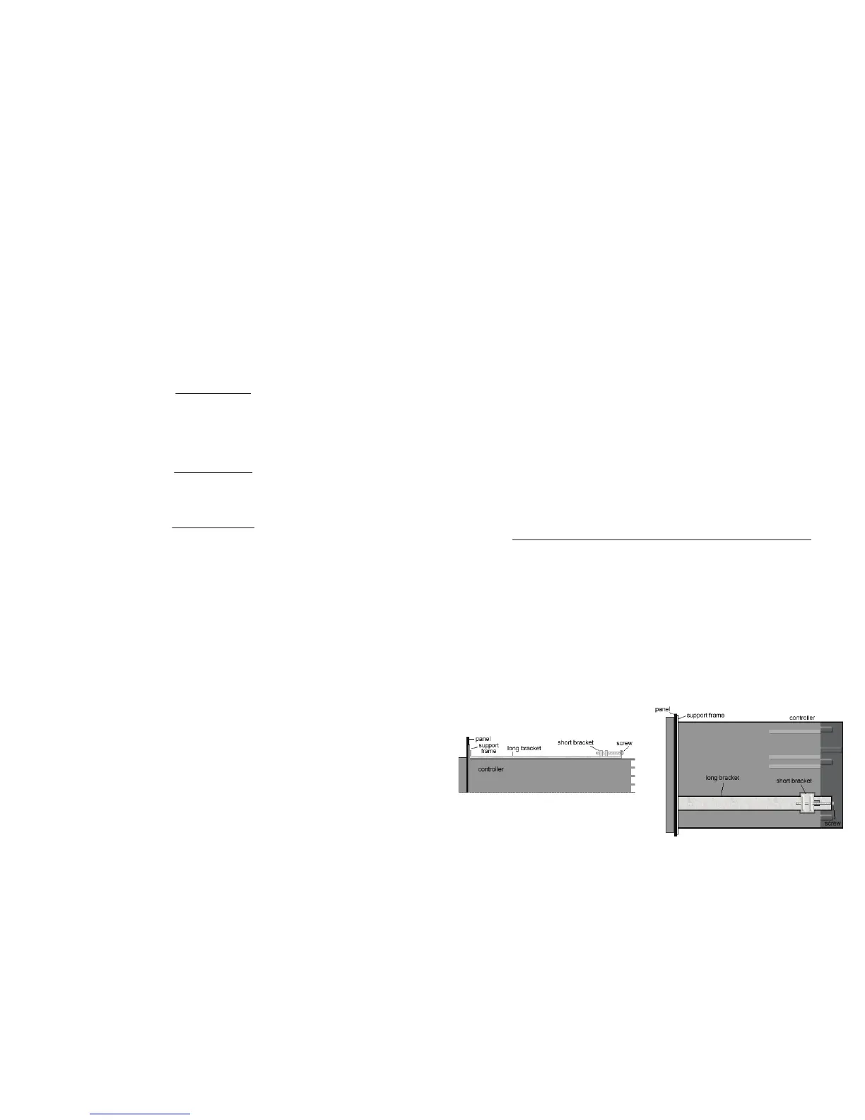
ATTACHING THE MOUNTING BRACKETS
1. Slide the controller through the hole in the panel.
2. From the rear of the controller, slide the metal square support frame over the controller, so that it is
pressed against the interior of the panel.
3. If not assembled, on the top of the controller, place one long bracket with the ridge side facing up.
Insert the short bracket into the slots on the controller, so that it ts snugly against the long bracket.
4. Slide the long bracket towards the controller face, so that the front end is pressed against the support
frame (or the panel, if not using the support frame).
5. Secure a screw from the hole in the long bracket through the hole in the short bracket. Tighten, but
do not overtighten.
6. Do the same for the bracket on the bottom of the controller. Tighten both brackets equally.
SIDE VIEW (of the top bracket)
TOP VIEW
 Loading...