Page 9;&(%$*4.8"4,7%<'*#$"&8#=%/7*,#*%4,77%>?@@@?@AA?BCDC1Item 57056
EF;6GHIJ6KFGLIMNFLMG6MFMO6 E6GPJ
;"3'(*%S-%%E$,$"&8,(V%F"(%E'//7V%E*$'/
!
"
" #
$%%%
&
&
"+,-./0123%
4''*5
7
7
8
8
9
6
:
;
<
=*'>2
:
?
@
&
A%
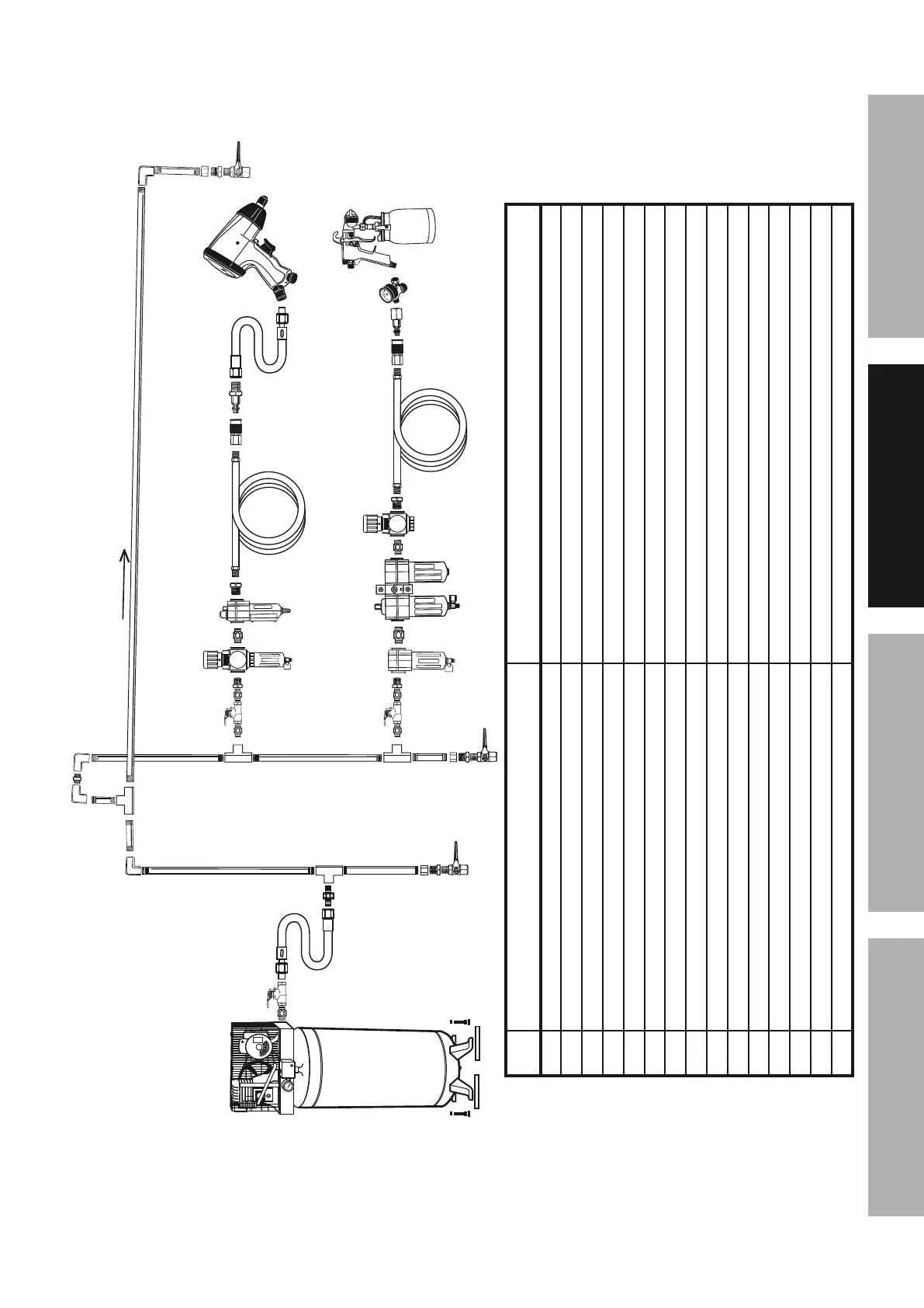
U*#4("/$"&8 ;'84$"&8
A Vibration Pads For noise and vibration reduction
B Anchor Bolts Secures air compressor in place
C Ball Valve Isolates sections of system for maintenance
D Isolation Hose For vibration reduction
E Main Air Line - 3/4″ minimum recommended Distributes air to branch lines
F Ball Valve To drain moisture from system
G Branch Air Line -1/2″ minimum recommended Brings air to point of use
H Air Hose Connects air to tool
I Filter Prevents dirt and condensation from damaging tool or workpiece
J Regulator Adjusts air pressure to tool
K Lubricator (optional) For air tool lubrication
L Coupler and Plug Provides quick connection and release
M Leader Hose (optional) Increases coupler life
N Air Cleaner / Dryer (optional) Prevents water vapor from damaging workpiece
O Air Adjusting Valve (optional) For fine tuning airflow at tool
 Loading...