Do you have a question about the Honda CRF1000 and is the answer not in the manual?
Explains the purpose and scope of the service manual.
Provides crucial safety precautions for performing service procedures.
Details essential safety measures to prevent injury and damage.
Outlines the fundamental rules and guidelines for servicing the motorcycle.
Lists detailed technical specifications for various motorcycle components.
Provides essential torque specifications for fasteners used in engine and frame assembly.
Details the materials and locations for lubrication and sealing of motorcycle parts.
Lists specialized tools required for specific service procedures.
Explains the systems designed to control motorcycle emissions and their components.
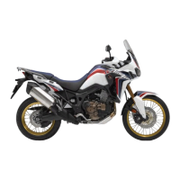
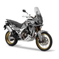
Highlights key technical features of the motorcycle, such as ABS and G Ride systems.
Covers general service aspects for body panels, exhaust, and sidestand.
Addresses common issues like excessive exhaust noise and poor performance.
Identifies the location and removal order of various body panels on the motorcycle.
Covers the removal and installation procedures for the muffler and exhaust pipe.
Details the steps for removing and installing the motorcycle sidestand.
Outlines the recommended schedule for periodic maintenance tasks.
Details the procedure for inspecting and adjusting valve clearance.
Covers engine oil level inspection and the recommended oil specifications.
Details the inspection and adjustment procedures for the drive chain slack.
Covers inspection of brake fluid levels, pads, and system for leaks.
Covers inspection and adjustment of front and rear suspension systems.
Details the inspection and service procedures for steering head bearings.
Offers general troubleshooting advice, including intermittent failures and DTC identification.
Lists Diagnostic Trouble Codes (DTCs) with their corresponding function failure and symptoms.
Provides detailed step-by-step procedures for diagnosing and resolving specific DTCs.
Covers the removal, installation, and inspection of the MAP sensor.
Details the removal, installation, and inspection procedures for the ECT sensor.
Explains the removal, installation, and inspection process for the IAT sensor.
Covers the removal, installation, and inspection of the VS sensor.
Details the removal, installation, and inspection procedures for the O2 sensor.
Explains the removal, installation, and inspection of the bank angle sensor.
Addresses common ignition system issues such as no spark at the plug.
Details the procedures for inspecting the ignition system, including spark plug and primary voltage checks.
Explains how to measure the ignition coil's primary peak voltage.
Covers the procedure for measuring the CKP sensor's peak voltage.
Details how to check and adjust the ignition timing.
Addresses common issues like the starter motor not turning or turning slowly.
Covers the procedure for removing and installing the starter motor.
Details the steps for removing and installing the starter relay switch.
Addresses common issues like the engine not starting or stalling.
Covers procedures for relieving fuel pressure and inspecting the fuel line.
Details the process for normalizing and testing fuel pressure.
Details the steps for removing and installing the fuel tank.
Covers the removal, installation, and inspection of the fuel pump unit.
Covers the procedure for removing the throttle body assembly.
Details the removal and inspection process for the Idle Air Control Valve (IACV).
Covers the removal and disassembly of the fuel injector assembly.
Addresses common cooling system issues like engine temperature too high or too low, and coolant leaks.
Details the process for replacing coolant and bleeding air from the system.
Covers the removal and installation procedures for the thermostat.
Details the steps for removing and installing the left and right radiators.
Covers the removal and installation process for the water pump.
Addresses common issues related to oil level, pressure, contamination, and emulsification.
Covers the procedure for measuring engine oil pressure using a gauge.
Details the steps for removing and installing the oil pump on CRF1000/A models.
Covers the procedure for removing and installing the oil pump on CRF1000D models.
Explains the process for removing and installing the oil strainer.
Addresses common engine top-end issues like low compression and excessive noise.
Details the procedure for measuring cylinder compression pressure.
Details the procedure for removing and installing the rocker arm assembly.
Covers the procedure for removing and installing the camshaft.
Details the steps for removing and installing the cylinder head.
Details the procedure for inspecting and adjusting valve clearance.
Provides general information and warnings regarding engine removal and installation.
Identifies the location of engine mounting points and related components.
Details the step-by-step procedure for removing the engine from the motorcycle.
Covers the procedure for installing the engine back into the motorcycle frame.
Addresses common issues related to steering, wheel wobble, suspension, and front suspension noise.
Covers the removal and installation of the handlebar and related controls.
Covers the procedure for removing and installing the front wheel.
Details the process of replacing the wheel bearings for both front and rear wheels.
Explains the steps for disassembling the front fork components.
Covers the removal and installation of the steering stem assembly.
Addresses common issues like steering alignment, wheel wobbling, and suspension stiffness.
Covers the procedure for removing and installing the rear wheel.
Details the process of replacing the wheel bearings using special tools.
Explains the disassembly and inspection of the cushion arm and connecting rod.
Covers the procedure for replacing pivot bearings using special tools and a hydraulic press.
Details the steps for removing and installing the swingarm assembly.
Addresses common brake issues like soft or spongy levers and brake drag.
Details the procedure for draining, replacing, and bleeding brake fluid.
Details the steps for removing and installing the front brake caliper.
Covers the procedure for removing and installing the rear brake caliper.
Explains the removal of parking brake pads and pins for CRF1000D models.
Details the steps for removing and installing the front brake master cylinder.
Covers the procedure for removing and installing the rear brake master cylinder.
Covers ABS pre-start self-diagnosis and general troubleshooting procedures.
Lists Diagnostic Trouble Codes (DTCs) for the ABS system with their failures and symptoms.
Provides step-by-step procedures for diagnosing DTCs related to ABS indicator and wheel speed sensors.
Details the procedure for removing and installing the ABS modulator assembly.
Addresses common issues like weak battery, current leakage, and charging voltage problems.
Covers the procedure for removing and installing the motorcycle battery.
Covers current leakage and charging voltage tests.
Details the procedure for removing and installing the regulator/rectifier.
Explains how to measure the resistance of the alternator charging coil.
Identifies the location of various lights, meters, and switches on the motorcycle.
Covers the procedure for removing and installing the headlight assembly.
Explains the steps for removing and installing turn signal lights and relays on CRF1000A/D.
Covers the procedure for removing and installing the combination meter.
Provides procedures for checking the TXD line for open or short circuits.
Covers inspection, removal, and installation of the ignition switch.
Details the process of checking continuity for handlebar switch connectors.
Covers the pre-start self-diagnosis and inspection of the HSTC system.
Identifies the location of HISS system components like ECM/PCM and immobilizer receiver.
Details the procedure for registering new transponder keys.
Addresses issues when the HISS indicator does not come on or stays on.
Covers checking the CKP sensor line connected to the ECM/PCM.
Provides the complete wiring diagram for the CRF1000 model.
Illustrates the wiring diagram for the CRF1000/A model.
Shows the wiring diagram specific to the CRF1000D model.
| Displacement | 998cc |
|---|---|
| Max Power Output | 70kW @ 7, 500rpm |
| Fuel System | PGM-FI electronic fuel injection |
| Starter | Electric |
| Final Drive | Chain |
| Wheelbase | 1, 575mm |
| Ground Clearance | 250mm |
| Fuel Capacity | 18.8L |
| Bore x Stroke | 92.0mm x 75.1mm |
| Transmission | 6-speed |
| Frame Type | Steel semi-double cradle |
| Front Suspension | Showa 45mm inverted telescopic fork with cartridge damper, adjustable compression and rebound damping and preload, 230mm stroke. |
| Front Brake | 310mm dual wave floating hydraulic disc with aluminium hub and radial 4-piston calipers |
| Rear Brake | 256mm single wave hydraulic disc with single-piston caliper |
| Front Tire | 90/90-21 |
| Rear Tire | 150/70-18 |
| Seat Height | 870mm |
| Engine Type | Liquid-cooled 4-stroke 8-valve parallel twin |