EasyManuals Logo

Honeywell 1026FF02F9 User Manual

Honeywell 1026FF02F9
83 pages
To Next Page IconTo Next Page
To Previous Page IconTo Previous Page
Page #71 background imageLoading...
Page #71 background image
Chapter 5 — About the GPIO Ports
62 IF1 Fixed RFID Reader User Manual
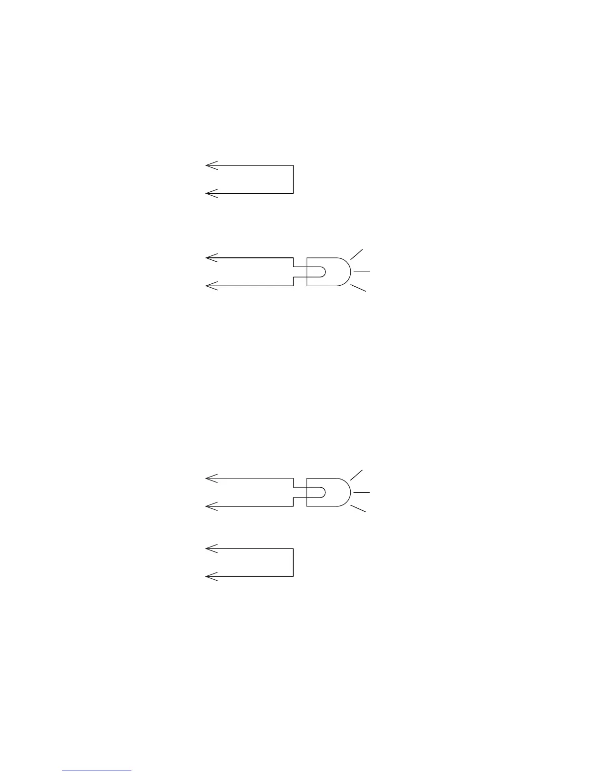
How to Switch the High Side with Reader Power
In this example, an external indicator lamp (0.25 A maximum current) is
connected to the -Output and Ground pins, and the corresponding
+Output pin is connected to the +12 VDC source.
Switching the High Side
How to Switch the Low Side with Reader Power
For low side switching applications, the lamp power is routed to all the
lamps in common and the low side of the load is routed to the switch.
Connect the external indicator lamp to the +Output and +12 VDC pins,
and short the corresponding -Output pin to ground.
Switching the Low Side of the Output Load
External
indicator lamp
0.25 A maximum
+Output
+12 V
Ground
- Output
External
indicator lamp
0.25 A maximum
Ground
- Output
+Output
+12 V

Table of Contents

Questions and Answers:

Question and Answer IconNeed help?

Do you have a question about the Honeywell 1026FF02F9 and is the answer not in the manual?

Honeywell 1026FF02F9 Specifications

General IconGeneral
BrandHoneywell
Model1026FF02F9
CategoryCard Reader
LanguageEnglish

Related product manuals