4 - 60
MAN0443.P65 Issue 13 Aug 04 5701 Control System
05701-M-5001 A02279
CHAPTER 4 - INSTALLATION INSTRUCTIONS
35
36
33
34
31
32
29
30
27
28
25
26
23
24
21
22
19
20
17
18
15
16
13
14
11
12
9
10
7
8
5
6
3
4
1
2
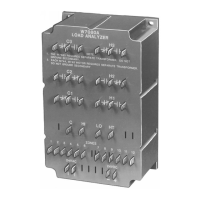
Relay/Field Interface Card
05701-A-0326
05701-A-0327
05701-A-0328
05701-A-0329
05701-A-0330
Arrows Indicate Direction of
Loop Current Flow
Single IS
Safety Barrier
x3
x3
CabinetTwo Core Screened Cable
Single Channel Control Card 4 - 20mA 05701-A-0301
Fitted With 4 - 20mA Sensor Drive 05701-A-0283
28
29NS
27
25GND
01
S
Protective
Earth
Loop + to Relay Card S
Loop - to Relay Card 01
Screen to Ground
Link Positions
LK10
LK13
LK4
LK1
Lifeline
IS Lifeline Sensor With Double Safety Barrier
Single Channel Control Card 4 - 20mA 05701-A-0301
Fitted With 4 - 20mA Sensor Drive 05701-A-0283
If the measuring resistance is in the negative supply line, a double
safety barrier must be used.
WARNING
Do not short the S and NS input lines since this
may cause damage to the Control Card input
circuit.

 Loading...