2-1
SECTION 2
Mounting and Wiring the Control
•••••••••••••••••••••••••••••••••
This section describes the procedures for mounting and wiring this control and its peripheral
devices. In the following subsections, procedures are listed in the left column, while notes
and pertinent explanations are provided in the right column.
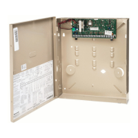
Mounting the PC Board
NOTE: The door of the metal cabinet may be
removed to make it easier to install the PC
board. Remove the door as follows:
1. With the cabinet laying on a flat surface,
swing open the door to its full-open position.
2. Slide the door out of its retaining slots in
the cabinet and store in a safe place.
3. Remove standoff (part number K0380) from
the hardware bag and insert it into the
square hole in the back of the cabinet so
that it will align behind the lower left
mounting hole in the PC board.
4. Insert top of circuit board into slots at top of
cabinet. Make sure that circuit board rests in
slots as indicated in the diagram shown below.
5. Swing base of circuit board onto the raised
cabinet tab and standoff.
6. Secure the sides of the PC board to the
enclosure using the 2 screws provided.
Notes
• Before installing the cabinet's contents, remove
the metal cabinet knockouts required for wiring
entry. Do not remove the knockouts after the
circuit board has been installed.
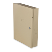
Cabinet and Lock
1. Mount the control cabinet to a sturdy wall
in a clean, dry area, which is not readily
accessible to the general public, using
fasteners or anchors (not supplied) with the
four cabinet mounting holes.
2. Remove cabinet door, then remove the lock
knockout from the door. Insert the key into
the lock.
3. Position the lock in the hole, making
certain that the latch will make contact
with the latch bracket when the door is
closed. When correctly positioned, push the
lock until it is held securely by its snap
tabs.
Notes
• The cabinet can be closed and secured without a
lock by using 2 screws in the cover's edge.
CABINET DOOR
BOTTOM
LOCKED
UNLOCKED
cab_lock_snap-001-V0
ADEMCO
ADEMCO
PUSH
SNAP
TAB
SNAP
TAB
PUSH
ON LOCK
UNTIL IT
IS SEATED
SECURELY
STEP 2STEP 1
CHECK
POSITION
Figure 1. Installing the Cabinet Lock

 Loading...