DT92 WIRELESS DIGITAL ROOM THERMOSTAT
7
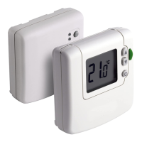
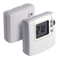
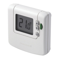
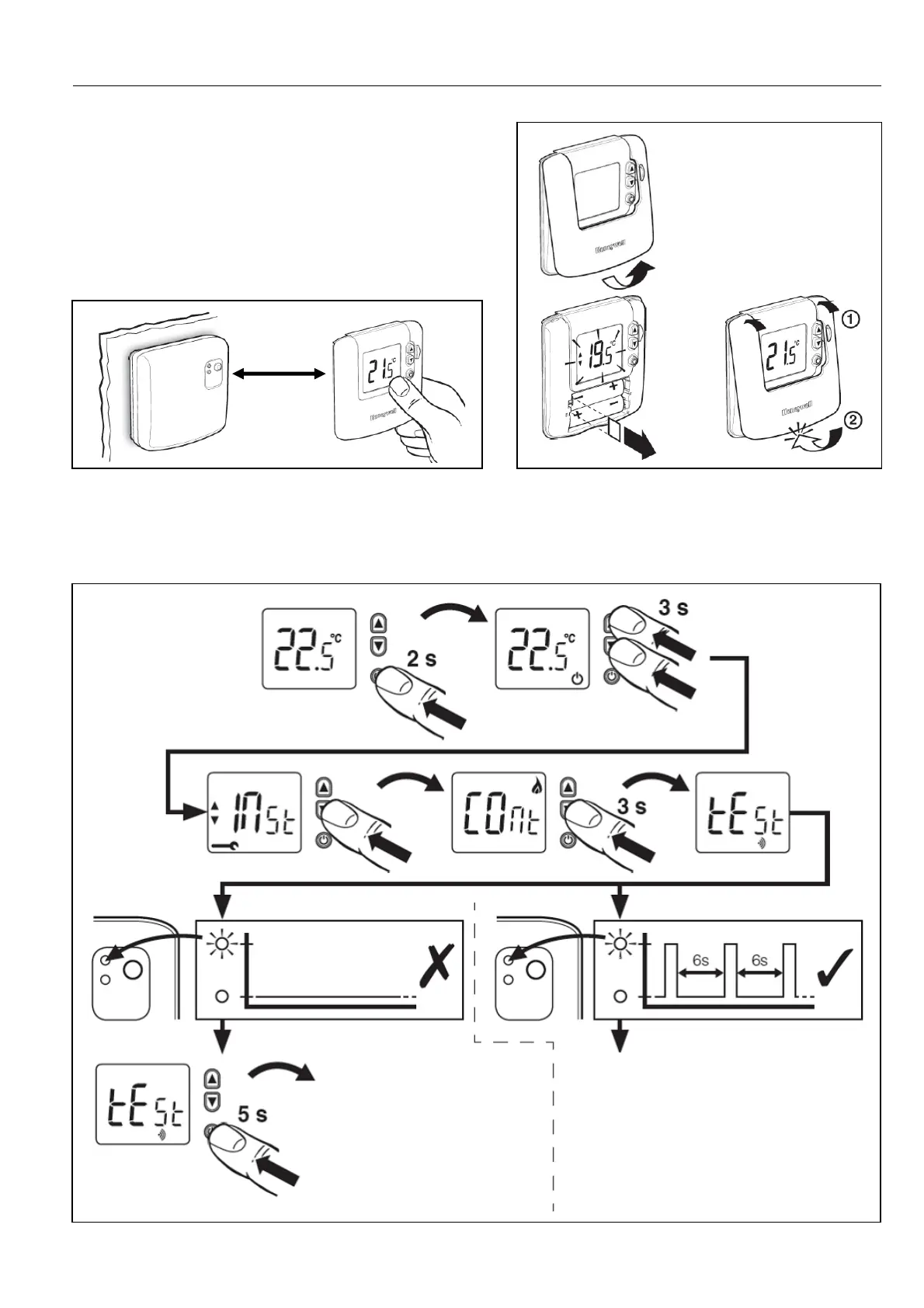
Installing the DT92 Room Thermostat
Before mounting the DT92 thermostat onto its
backplate, power it up by removing the battery tab.
Bring the DT92 thermostat to a distance 2-3 m from
relay box and initiate the RF Communication Test to
confirm the BDR91 relay box is wired correctly and that
both devices are bound (linked) to each other.
2 – 3 m
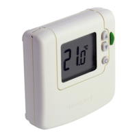
RF COMMUNICATION TEST
Initiate RF Communication Test by the following
sequence of actions applied to the DT92 thermostat.
If green LED does not
flash, units are not linked
and must be bound
together again.
If green LED flashes every 6
seconds, units are correctly
bound and a suitable location
for the DT92 thermostat can
now be identified.
 Loading...