Flex 402 & Flex 404 Instruction Manual — P/N 52194:D4 3/27/2015 13
Circuits Product Description
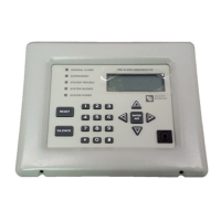
LED Indicators
• Fire Alarm Zone 1 - red LED
• Fire Alarm Zone 2 - red LED
• Fire Alarm Zone 3 - red LED (Flex 404 only)
• Fire Alarm Zone 4 - red LED (Flex 404 only)
• Supervisory Zone 1 - yellow LED
• Supervisory Zone 2 - yellow LED
• Supervisory Zone 3 - yellow LED (Flex 404 only)
• Supervisory Zone 4 - yellow LED (Flex 404 only)
• Trouble Zone 1 - yellow LED
• Trouble Zone 2 - yellow LED
• Trouble Zone 3 - yellow LED (Flex 404 only)
• Trouble Zone 4 - yellow LED (Flex 404 only)
• Maintenance Zone 1 - yellow LED
• Maintenance Zone 2 - yellow LED
• Maintenance Zone 3 - yellow LED (Flex 404 only)
• Maintenance Zone 4 - yellow LED (Flex 404 only)
• AC Power - green LED
• NAC Disable - yellow LED
• Zone Disable - yellow LED
• NAC Fault - yellow LED
• System Trouble - yellow LED
• Power Trouble - yellow LED
• Walktest - yellow LED
• Alarm Silence - yellow LED
• Earth Fault - yellow LED (on main circuit board) lights if zero impedance between FACP and
ground exists
• Battery Fault - yellow LED (on main circuit board)
• Charger Fault - yellow LED (on main circuit board)
Local Piezo Sounder
A piezo sounder provides separate and distinct sounds for alarm, trouble, maintenance and
supervisory conditions as follows:
• Alarm - on steady
• Trouble - pulse 1 second on and 1 second off
• Maintenance - pulse ½ second on and ½ second off
• Supervisory - pulse ½ second on and ½ second off
1.4 Circuits
Input Circuits
Two input IDCs (Initiating Device Circuits) on the Flex 402 and four IDCs on the Flex 404 provide
Style B (Class B) configurations. All IDCs accept i
3
detectors as well as conventional two-wire
smoke detectors, four-wire smoke detectors and normally-open contact devices.
Output Circuits
• 24 VDC resettable special application power output - 500 mA
• 24 VDC nonresettable special application power output (Flex 404 only) - 500 mA

 Loading...


