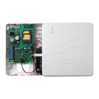
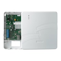
GSMX Installation and Setup Guide
– 25 –
Cell BaseSt
Chan
xxxxx x
xxx
GSM Status Display Screen 3
Cell – Base Station ID
BaseSt – Base Station Antenna Sector
Chan – Control Channel in use
Press the [Space] key to go to the next screen.
Press the [BS] key to go to the previous field.
Second Site
RSSI
-xxxdbm
GSM Status Display Screen 4
Secondary GSM Site RSSI level in dbm.
Press the [Space] key to go to the GSM Status
Display Screen 1.
Press the [backspace] key to go to the previous
field.
[S]
ECP Flt
OK
ECP Mode
Displays the mode of operation and system fault
status.
Flt – Represents communicator faults:
OK = Normal, No fault.
G = No network connectivity over GSM and fault
time has expired.
g = No network connectivity over GSM and fault
time has NOT yet expired.
[T]
Test Msg
Sent
Test Alarm
Sends a Test alarm to AlarmNet. Functional for
a registered GSMX only. If the device is not
registered, a message is displayed indicating
that the command cannot be executed.
[X]
Reset CPU
Y/N
Reset the GSMX.
Pressing [N] returns to normal mode.
Pressing [Y] resets the device.
[Shift]
[↑]
(UP
arrow)
Registering
…
Registration
Registers a programmed GSMX with AlarmNet.
[↓]
(DN
arrow)
Enter PIN#
Registration with PIN for Replacement
Module
Registers a replacement GSMX with AlarmNet,
once programmed, using the existing PIN #.
 Loading...
