Installation
2/03 10260A Series Actuators – Installation, Operations, and Maintenance 19
Rod end, nut and bolt are
supplied with the actuator
1/2"-20 right-hand threads
1/2"-20 left-hand threads
Customer supplied nut and bolt
24 to 120 inches
Customer supplied pipe*
* cut to size
with
standard NPT both ends
a/n 23202
Figure 3-8 Pipe Linkage Kit
*Pipe length = Overall linkage length minus (-) 17 inches (43 cm).
Actuator Crank Arms
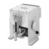
The 10260A Series Actuator comes standard with a 5” crank arm (p/n 51309967-501) or an optional crank
arm adjustable 0”-12” (p/n 51452160-501).
The 10260A Series Actuator crank arm uses a standard ½” rod end to compliment the turnbuckle and pipe
linkage kits. The crank arm connects the link rod using a ½” rod end and a hex link rod adapter. For
applications which use a link rod, a link rod adapter is available is available as an option in the Model
Selection Guide.
1/2" Rod End
Link Rod Adapter
Link Rod
Set Screws
Insert the Link Rod Completely into the Link rod
Adapter and tighten the (2) set screws with
suff i ci ent f o
ce to hold the link
od.
Figure 3-9 Standard 5” Crank Arm

 Loading...


