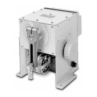
10260A Series Actuators Installation, Operations, and Maintenance Manual
22 10260A Series Actuators – Installation, Operations, and Maintenance 2/03
3.4.2 Customer Connections
WARNING
!
The ground terminal must be connected to a reliable earth ground.
WARNING
!
While the unit is powered, a potentially lethal shock hazard exists inside the case. Do not open the case
while the unit is powered. Do not access the terminals while the unit is powered.
Figure 3-11 and Figure 3-12 show all the available connections for the 10260A Series actuator (non-contact
sensor).
NO
SW2
33
24
15
OUTPUT CURRE NT
0-20mAdc
4-20mAdc/
NO
4-20mAdc
RE SISTOR IS
MOUNTED ON
TERMINAL BOARD
30
CLOSED WHEN
"NOT -IN- A UTO "
SWITCH CONTACT
AUTO/MAN
28 29
-
INP UT
OUTPUT
250 >
31
-
32
HOT
PE
NEUTRAL
CONTROLLER
50/ 60 H z
120 V/ 24 0VA C
SUP PLY /
MAINS POWER
1413121110
INTERNA L
CONNECTIONS
21
NO
2019
NC
C
SW4
2322
NC
C
SW5
SW1
NO
3L N 4
SW2
NC
5
SLIDEWIRE EMULATION
36
L
34
FB
35
H
181716
NO
27
NO
2625
NC
C
SW6
NC C
SW3
SW2
COM
NC
SW1
6 7
SW1
COM
8
9
"USE COPPER CONDUCTORS ONLY"
RESISTOR TO BE MOUNTED AT INPUT OF
CUSTOMER'S INSTRUMENT
UP
DOWN
CONTROLLER
DRIVE
Figure 3-11 Customer Terminal Connections (Non-contact sensor)

 Loading...


