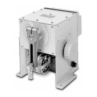
10260A Series Actuators Installation, Operations, and Maintenance Manual
32 10260A Series Actuators – Installation, Operations, and Maintenance 2/03
0%
100%
8 (SW1 COM) 9 (SW2 COM)
7
NC
NC
155
14
Left hand
Pointer scale
SW#1
SW#2
End of travel limit switch settings
Clockwise and counterclockwise rotation is the direction of the output shaft when facing the end
of the shaft. As shown, clockwise rotation of the output shaft activates SW#1 (at 0% on left hand
pointer scale) and CCW rotation activates SW#2 (at 100% on left hand pointer scale). Terminal
numbers are next to circles (see Figure 3-11).
Figure 4-2 End of Travel Limit Switch Settings
Figure 4-3 Auxiliary Switch Settings

 Loading...


