10260A Series Actuators Installation, Operations, and Maintenance Manual
50 10260A Series Actuators – Installation, Operations, and Maintenance 2/03
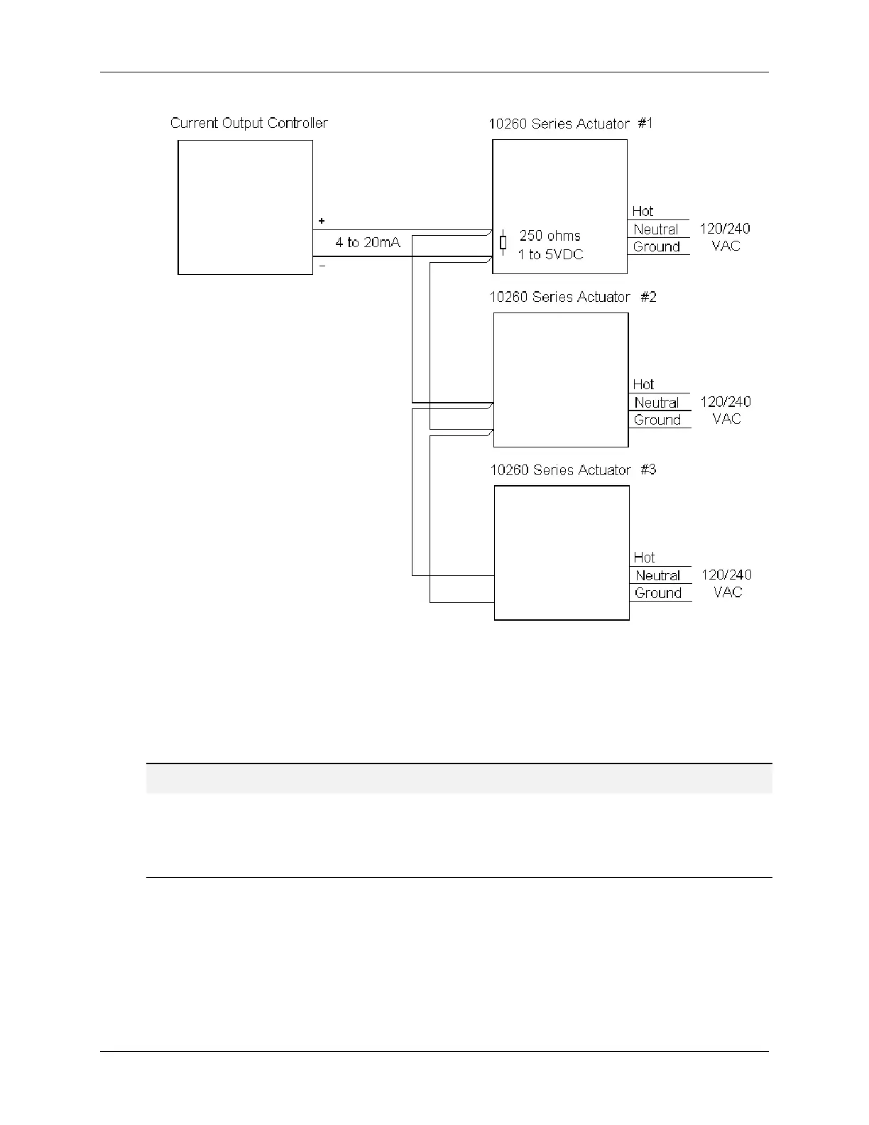
Figure 6-4 Multiple Actuator Interconnection Diagram
REFERENCE
The minimum recommended “zero” adjustment is 0.2 V. Below 0.11 V the positioner assumes a loss of
signal and will drive the actuator to the customer selected position. The maximum zero adjustment is 3.0 V
if full travel is desired (span set at 5.0 V). Minimum span setting is 1.0 V, maximum span setting is 5.0 V.
To insure failsafe action, in the event that the input is disconnected, a 10 K-ohm bleeder resistor should be
placed across the input terminals.

 Loading...