INTELLIGUARD 9000™
74-3047—110
Loop Parameters and Programming
The followin
parameters define the possible loop
pro
rammin
t
pes:
Parameter 0: Default value = 0.
— 0 = The seven se
ment displa
is inactive when the tamper
switch is pressed.
— 1 = The seven se
ment displa
remains active when the
tamper switch is pressed.
Parameter 1: Default value = T
pe 2.
— Parameters 1 throu
h 6 are loop t
pe 0, 2, 3 or 4. Refer to
Fi
. 10.
Parameter 7: Default value = 0.
— 0 = Keep pro
rammed loop t
pes when exitin
Pro
ram
Mode.
— 1 = Return to default loop t
pes when exitin
Pro
ram
Mode.
There are four possible combinations of loops and end-of-line
resistors. Each loop ma
be independentl
pro
rammed for
an
of the loop t
pes shown in Fi
. 10.
To set loop t
pe:
a. Press switch
S3
QUIT
to return to
C
on the displa
.
b. Press
S1 (NEXT)
until the LED flashes
P
.
c. Press
S2
to accept PROGRAM mode.
d. Press
S1
to scroll throu
h the loops to loop 1.
e. Press
S2
to accept pro
rammin
for the selected
loop. The decimal point li
hts in the bottom ri
ht cor-
ner of the LED displa
DS1
to indicate the selected
loop t
pe number.
f. Press
S1
to scroll to the desired loop t
pe number,
as shown in Fi
. 10.
.Press
S2
to accept the desired loop t
pe number
and displa
the next loop.
h. Repeat steps e. throu
h
. for each loop.
i. Press
S3 (QUIT)
to leave PROGRAM mode.
Fig. 10. Possible loops, circuits for BIC-6 device.
COMMUNICATION AND ALARM DISPLAY
The BIC-6 has three modes:
—
P
allows the user to pro
ram the confi
uration of the
individual loops.
—
C
enters the Communication Displa
mode and causes the
center bar
RECEIVE
on the LED displa
to li
ht each
time the BIC-6 receives communication from the CU. The
bar closest to the terminal
TRANSMIT
li
hts each time
the BIC-6 responds.
—
A
enters the
Alarm Display
Mode for the loops. If the loops
are normal, a bar displa
s
—
on the LED. If the loop is in
alarm, the loop number appears on the LED displa
and
the decimal point li
hts;
for example,
4.
for loop four. If
the loop is in trouble, the loop number appears on the LED
displa
, but the decimal point is not lit;
for example,
5
for
loop five. If more than one loop is abnormal, the displa
scrolls to show each abnormal loop for one second.
Alarm Status Display Examples
— Indicates normal status for all loops.
2 Indicates trouble on loop 2.
4
.
Indicates alarm on loop 4.
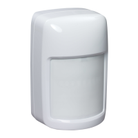
2-Input Concentrators (BIC-2), 2-Input Concentrators
with Hold-up (BIC-2 HU)
NOTES:
— The BIC-2 and BIC-2 HU are functionall
ver
similar. The same dia
rams appl
to both devices.
The
differ in that the BIC-2 HU has red buttons
and the Hold-up function must be pro
rammed
into the I9000 CU, while the BIC-2 has white but-
tons and can be used for an
purpose other than
the Hold-up function. The BIC-2 can be pro-
rammed accordin
l
in the I9000 CU.
N.C.
N.C.
TAMPER
CONTACT
N.C.
CONTACT
2.2K
5%
1/4W
2.2K, 5%, 1/4W
N.C.
N.O.
TAMPER
CONTACT
2.2K
5%
1/4W
LOOP +
LOOP –
LOOP +
LOOP –
+12 VDC
LOOP –
LOOP +
LOOP –
SHORT
2.2K = NORMAL
4.4K = ALARM
OPEN = TROUBLE
SHORT = ALARM
2.2K = NORMAL
OPEN = TROUBLE
SHORT = NORMAL
OPEN = ALARM
CIRCUIT FOR ULC INSTALLATIONS USING A NORMALLY
OPEN CONTACT WITH END OF LINE RESISTOR.
CIRCUIT USING A NORMALLY CLOSED
CONTACT WITH END OF LINE RESISTOR.
LOOP +
LOOP –
N.O. N.C.C
ADDITIONAL RELAY
OR
A REGULAR LED CAN BE CONNECTED ACROSS LOOP INPUTS.
NO SERIES RESISTOR REQUIRED WITH LED (RESISTOR
PROVIDED INTERNALLY).
LOOP "+" INPUT NOT USED.
CONNECT OUTPUT RELAY
BETWEEN "–" LOOP INPUT
AND "+12 Vdc"
UNSUPERVISED CLOSED LOOP
DESCRIPTIONTYPE TYPICAL LOOP SCHEMATIC (FIVE LOOPS)
0
LOOP
TYPE
LOOP
TYPE
LOOP
TYPE
LOOP
TYPE
2
3
4
M16078E
= TROUBLE (VERSION 006 OR HIGHER)
= ALARM (VERSION 005 OR LOWER)
 Loading...