N
KHF 1050 SYSTEM INSTALLATION MANUAL
Page 37
Revison 2 23-10-09 Apr/2006
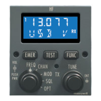
3.C.(6) RM-855 RMU, Leading Particulars
NOTE: Refer to the RM-855 RMU Component Maintenance Manual P/N
A09-3800-028 for more description of the RM-855. Only RM-855 part
numbers 7013270-951, -952, -967, and -968 offer HF COM capability.
Table 36 - RM-855 Leading Particulars
4. System Function
4.A. System Functional Overview
The KHF 1050 HF Communication System supports a wide variety of
communication requirements. The major components of the KHF 1050 HF system
are listed below:
• KAC 1052 Antenna Coupler
• KPA 1052 Power Amplifier
• KRX 1053 Receiver/Exciter
• Compatible Control Display Unit (CDU)
The basic KHF 1050 HF system is a mobile communication system for aircraft. It
operates in a frequency range between 2.0 and 29.9999 MHz offering several
different emission modes to provide voice communication.
CHARACTERISTIC DESCRIPTION
Weight: Refer to “Figure 2022 - RM-855 Radio Management Unit
Outline and Mounting”
Dimensions: Refer to “Figure 2022 - RM-855 Radio Management Unit
Outline and Mounting” .
Temperature Range:
Operating:
Storage
-20 to +55 °C
-55 to +85 °C
Power Requirements: 28 Vdc nominal, 50 VA maximum
Connector: Refer to “Figure 2013 - RM-855 RMU Connector (144J1)
Pin Configuration” (J144P1) and “Table 2005 - RM-855
RMU Connector (144J1) Pin Definitions” .
 Loading...


