Home
Honeywell
Touch Panel
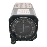
KI 208
Page 22 (KI 209 System Interconnect Diagram)
Honeywell KI 208 - KI 209 System Interconnect Diagram
26 pages
Manual
To Next Page
To Next Page
To Previous Page
To Previous Page
Loading...
BENDIX/KING
KI 208, KI 209
Re
v 4,
A
ug 2002
IM 006-001
40-0004
P
age 2-
15
FIGURE
2-8 KI
209 Sy
stem Int
erconnect
(Dwg No 1
55-0124
1-0000
, Rev 4)
RELEASED FOR THE EXCLUSIVE USE BY: AIRCRAFT ELECTRONICS ASSOCIATION
UP536434
21
23
Table of Contents
Main Page
Table of Contents
5
Introduction
7
Technical Characteristics KI 208, KI
7
Equipment
7
Units and Accessories Supplied
8
Description
9
Accessories Required, but Not
9
License Requirements
9
Requirements for Tso'D VOR/ ILS/ Glideslope
9
Deflection
11
General
11
Unpacking and Inspecting Equipment
11
Installation KI 208, KI 209
11
Post Installation Checkout
12
Deflection
12
Crimping Tool
12
ILS Deflection
13
KI 208 Pinout
15
KI 209 Pinout
16
KI 209 System
22
Related product manuals
Honeywell KI 209
26 pages
Honeywell Gent Vigilon A3 Mimic
4 pages
Honeywell SmartLine RMA801
144 pages
Honeywell SmartLine RMA800
144 pages