8 MagneW 3000
PLUS
Specification and Application Guide 1/98
Electrical Connection Considerations
For electrical connections of the
converter/detector the following should
be checked:
• Cable types
• Laying of cables
• Cable lengths
• Grounding
Cable Types
The standard cables for the instrument
are as follows:
•
Signal cable:
2-core individually
double-shielded cable
•
Excitation cable:
2-core chloroprene
cabtyre cable
If standard cables are unavailable,
contact Honeywell for
recommendations.
Laying of Cables
• Do not lay the cables near a motor, a
transformer, or a large-current cable
which may cause induction noise.
Lay the cables 1 meter (3.3 feet) or
more away from heavy-duty power
cables.
• Lay the signal cable in a metallic
conduit, a flexible tube, or a duct,
separately from the excitation current
cable or any other power cables.
• Wire with electrical tube and duct to
keep out water and protect the wire
from external damage. Lay the tube
so that no water gets into the unit.
• Use a waterproof gland at the conduit
connection.
• Do not employ any junction point for
connection of the signal cable or the
exciting cable between the detector
and the converter. When it is
unavoidable to employ a junction
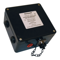
point, use Cable Junction Box (Part
No. 80720002-000) which has been
designed specifically for this
purpose.
• Do not short the excitation current
terminals X and Y of the converter.
Cable Lengths
• The length of the cable between the
detector and the converter depends
on the electrical conductivity (µS/m)
of the fluid to be measured. (Refer to
Figure 9 on page 10.)
In general, the electrical conductivity
of potable water or sewage water is of
a level of 10000 µS/m (100 µΩ/cm).
Therefore, for a detector of 15 mm
(0.6 in.) diameter or over, the
maximum allowable cable length is
300 meters (984 feet).
• Signal Cable
If a signal cable is required to be laid
more than 500 meters (1640 feet),
select a cable cross section so that
the voltage drop in the cable does not
exceed 5V.
To calculate the excitation cable
cross section area, use the following
formula:
A (cross section area: mm
2
) =
35.6 x L (cable distance: m) x 0.4 (A)
1000 x 5 (V)
• Current output cable (4-20 mA)
The allowable current output load of
the converter is 0 to 600Ω. The sum of
the cable resistance plus load
resistance must be within this range.
With a 2 mm
2
(0.003 in
2
) cable, the
cable resistance for both-ways
between 1 km (3.281 ft.) distance is
approximately 20Ω. When the
receiver load is 400Ω, the current
output cable can be extended up to 10
km (6.2 miles).
• Pulse output cable
Can be extended up to 1 km
(3,281 ft.).
Grounding
• The grounding circuit should be less
than 100Ω.
• At the converter side, ground the
meter at the E terminal of the terminal
block or the ground terminal of the
case. The E terminal and the ground
terminal are mutually connected in the
unit.

 Loading...
