Do you have a question about the Honeywell PEHA Compact 952 JRM and is the answer not in the manual?
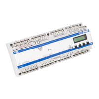
Details the physical layout and primary operational capabilities of the Compact 952 JRM module.
Covers critical electrical safety warnings, authorized electrician requirements, and mandatory safety practices.
Navigating the device menu, understanding core settings, and initial setup procedures.
Setting up timed operations for motors, including run direction and specific activation times.
Configuring the internal clock, date, and automatic adjustment for daylight saving time.
Procedure for selecting the preferred language for the device's display and interface.
Setting the duration for which motors operate when activated, measured in seconds.
Defining motor types (shutter, blind, awning) and associated adjustment times for optimal function.
Assigning individual motors to control groups (0, 1, 2) for synchronized actions.
Configuring automatic operation using timers, twilight, or sun sensors.
Assigning sensors like wind or sun, and setting motor lowering times based on sensor input.
Configuring the wind sensor's behavior and locking mechanisms to protect motors.
Setting the operational mode for Group 2, choosing between standard or sensor-based control.
Setting time delays between motor activations to prevent simultaneous operation.
Configuring broadcast modes (Master/Slave) and managing external sensor data communication.
Instructions for restoring factory defaults and checking the installed software version.
Overview of the JRM's capabilities for controlling blinds, shutters, and awnings.
How pushbutton inputs control motors in Central, Group, and Automatic modes.
Functionality of timers, twilight, sun, and wind/rain sensors for automated motor control.
Critical safety guidelines for electricians during the installation and commissioning process.
Instructions for physically mounting the 952 JRM unit onto a standard 35mm top hat rail.
Guidelines for connecting multiple JRM modules via the compact bus system.
Steps to diagnose and resolve issues in new or existing system installations.
Addressing Electromagnetic Compatibility problems through proper wiring and device placement.
Diagnosing and fixing problems related to motor movement direction or lack of operation.
Instructions for environmentally sound disposal of the device as electronic waste.
Details the warranty coverage, duration, exclusions, and claim procedures.
Provides PEHA's contact details for customer support and inquiries.
| Operating voltage 952 JRM | 100-240V~ /50-60Hz |
|---|---|
| Fusing the supply lines | Circuit breaker rated for 10 A, maximum |
| PHC supply voltage for compact system | Nom. 24 V DC (SELV), 21-28 V DC (Ripple voltage 5 %) |
| Power consumption (Standby) | approx. 2 W |
| Sensor connection | 24 V DC / 100 mA |
| Input signals | > 40ms |
| Max. length of 24V signal line | 400m at d = 0.8 mm (flexible or rigid wiring max. 1x 1, 5 mm²), Stripped length = 8 mm |
| Motor load per output | 100-240V~ /50-60Hz max. 1A |
| Input resistance | 1 kΩ |
| Contact resistance of inputs | Max. 33 Ohm (corresponds to < 1V DC at 24 mA) |
| Conductor cross–section of 230V lines | Flexible wiring: max. 1x 1, 5 mm², Rigid wiring: max. 1x 2, 5 mm², Stripped length = 8 mm |
| Ambient temperature | +10° to +40°C |
| Storage temperature | –20° to +60°C |
| Protection level | IP20 |
| Test specifications | EN 60669-2-1, EN 50428 |
| Certifications | CE, KEMA |
| Dimensions | width = 216mm (12TE), height = 55mm |
|---|