.
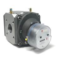
Figure 14. Change gear removal Figure 16. IN-S10 pulser installed
Meter Gear Color
3.5M/G65 White
5.5M/G100 Dark Green
9M/G160 Green
14M/G250 Red
Table 1
Fi
g
u
r
e
1
5
.
I
n
d
e
x
,
change
gear and
l
o
c
k
i
n
g
c
o
ll
a
r
8.
I
n
s
t
a
ll
the
r
e
p
l
a
c
e
m
e
n
t
i
n
d
e
x
.
•
Or
i
e
n
t
the
i
n
d
e
x
so the
m
oun
t
i
n
g
ho
l
e
s
li
n
e
up w
i
t
h
the posts
i
n
the base
p
l
a
t
e
.
•
C
a
r
e
f
u
ll
y
ensure the
s
h
a
f
t
on the
magnet
ho
l
d
e
r
i
s
i
n
the support
ho
l
e
on the
i
n
d
e
x
f
r
a
m
e
[
Fi
g
u
r
e
1
3
]
.
•
I
n
s
t
a
ll
the three screws to
r
e
t
a
i
n
the
i
n
d
e
x
to the
b
a
s
e
p
l
a
t
e
.
T
i
g
h
t
e
n
to
s
nu
g
.
9.
I
n
s
t
a
ll
i
n
d
e
x
m
a
s
k
i
n
g
p
l
a
t
e
.
1
0
.
I
n
s
t
a
ll
i
n
d
e
x
c
o
v
e
r.
11
.
I
n
s
t
a
ll
s
e
c
u
r
i
ty
s
e
a
l
s
.
12. Pulser (“Form A” Contact Closure Device)
All RABO
meter
i
n
d
e
x
e
s
can be
e
a
s
il
y
ou
t
f
i
tt
e
d
w
i
t
h
a
p
u
l
s
e
ou
t
p
u
t
d
e
v
i
c
e
to
i
n
t
e
r
f
a
c
e
w
i
t
h
a
u
x
ili
a
r
y
e
q
u
i
p
m
e
n
t
.
I
n
s
t
a
ll
a
t
i
on
o
f
a
p
u
l
s
e
r
i
s
q
u
i
c
k
and easy, and
r
e
q
u
i
r
e
s
no
d
i
s
a
ss
e
m
b
l
y
.
T
o
i
n
s
t
a
ll
a pulser, simply slide the pulser into
the slot on the index cover [Figure 16], and connect the wires
to the desired auxiliary devices
[
Fi
g
u
r
e
1
7
]
.
T
h
e
p
u
l
s
e
r
can be
secured to the
i
n
d
e
x
cover screw w
i
t
h
a
s
e
a
l
w
i
r
e
to
m
i
t
i
g
a
t
e
and
i
n
d
i
c
a
t
e
t
a
m
p
e
r
i
n
g
.
!
W
ARNING
E
x
p
l
os
i
o
n
H
a
z
a
r
d
A
ux
ili
a
r
y
e
q
u
i
p
m
e
n
t
and
i
n
t
e
r
c
o
nn
e
c
t
i
n
g
w
i
r
i
n
g
must be
i
n
a
cc
o
r
d
a
n
c
e
w
i
t
h
l
o
c
a
l
and n
a
t
i
o
n
a
l
codes
f
o
r
h
a
z
a
r
d
o
u
s
a
r
e
a
s
.
Figure 17. Pulser Connections
 Loading...