EasyManua.ls Logo

Honeywell RABO G65 - Thermowell Installation; Instrument Drive (ID); Retrofit a CTR meter with an Instrument Drive (ID)

Honeywell RABO G65
20 pages
To Next Page IconTo Next Page
To Previous Page IconTo Previous Page
Loading...
ELSTER
RABO
®
Rotary
Gas Meter
15 Honeywell
13.
Thermowell
All RABO
meters come
e
q
u
i
pp
e
d
w
i
t
h
two
(
2
)
¼
NP
T
a
u
x
ili
a
r
y
ports on the meter body
[
Fi
g
u
r
e
1
8
]
,
w
h
i
c
h
can be used
f
o
r
s
e
n
s
i
n
g
pressure
and
t
e
m
p
e
r
a
t
u
r
e
o
f
the
f
l
o
w
i
n
g
gas. A
t
h
e
r
m
o
w
e
ll
i
s
r
e
q
u
i
r
e
d
when
u
s
i
n
g
a
t
e
m
p
e
r
a
t
u
r
e
s
e
n
s
i
n
g
d
e
v
i
c
e
.
T
h
e
r
m
o
w
e
ll
s
are
a
v
a
il
a
b
l
e
as
a
cc
e
ss
o
r
i
e
s
to the
m
e
t
e
r.
NPT AUXILIARY PORTS
14.
Instrument
Drive (ID)
All RABO
meters can be
r
e
t
r
o
f
i
tt
e
d
w
i
t
h
an
i
n
s
t
r
u
m
e
n
t
d
r
i
v
e
,
or
i
n
s
t
r
u
m
e
n
t
a
d
a
p
t
o
r
p
l
a
t
e
.
T
h
e
I
D
p
r
o
v
i
d
e
s
a
m
oun
t
i
n
g
s
u
r
f
a
c
e
f
o
r
i
n
s
t
r
u
m
e
n
t
s
r
e
q
u
i
r
i
n
g
m
e
c
h
a
n
i
c
a
l
r
o
t
a
t
i
on
a
l
i
n
p
u
t
.
T
h
e
d
r
i
v
e
rate
o
f
the
RABO ID
i
s
1
0
c
u
b
i
c
f
ee
t
per
1
r
e
v
o
l
u
t
i
on
i
n
a
c
l
o
c
k
w
i
s
e
d
i
r
e
c
t
i
on
.
When
i
n
s
t
a
lli
n
g
an
i
n
s
t
r
u
m
e
n
t
,
o
r
i
e
n
t
the
i
n
s
t
r
u
m
e
n
t
f
a
c
e
to the FRONT edge
o
f
the
a
d
a
p
t
o
r
p
l
a
t
e
.
T
h
e
threads
i
n
the
a
d
a
p
t
o
r
p
l
a
t
e
f
o
r
i
n
s
t
r
u
m
e
n
t
m
oun
t
i
n
g
are
5
/
1
6
-
1
8
.
Fi
g
u
r
e
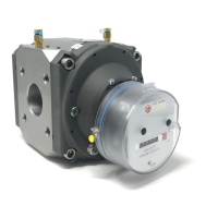
1
9
.
RABO
w
i
t
h
I
n
s
t
r
u
m
e
n
t
D
r
i
v
e
Fi
g
u
r
e
1
8
.
A
u
x
ili
a
r
y
p
o
r
t
s
a
)
I
n
s
t
a
lli
n
g
a
T
h
e
r
mo
w
e
ll
1.
If
meter
i
s
not
i
n
s
t
a
ll
e
d
i
n
the gas
p
i
p
i
n
g
,
go to
Step
5
.
2.
S
l
o
w
l
y
open bypass
v
a
l
v
e
.
3.
S
l
o
w
l
y
c
l
o
s
e
the
m
e
t
e
r
s
ou
t
l
e
t
v
a
l
v
e
,
then the
i
n
l
e
t
v
a
l
v
e
.
4.
S
l
o
w
l
y
,
c
o
m
p
l
e
t
e
l
y
d
e
p
r
e
ss
u
r
i
z
e
the meter
p
i
p
i
n
g
.
5.
R
e
m
o
v
e
one
o
f
the
p
l
u
g
s
i
n
the meter body by
u
s
i
n
g
a
¼
hex key.
6.
A
pp
l
y
T
e
f
l
on
tape or
p
i
p
e
dope to the
m
a
l
e
threads
o
f
t
h
e
t
h
e
r
m
o
w
e
ll
.
W
i
p
e
excess
p
i
p
e
dope
off
the
t
h
e
r
m
o
w
e
ll
probe and
l
e
a
d
i
n
g
threads to ensure no
p
i
p
e
d
o
p
e
enters the
m
e
t
e
r
i
n
g
c
h
a
m
b
e
r.
7.
Screw
the
t
h
e
r
m
o
w
e
ll
i
n
t
o
the meter and
t
i
g
h
t
e
n
to
1
8
f
t
-
l
b
s
.
8.
R
e
-
p
r
e
ss
u
r
i
z
e
the meter as
i
n
s
t
r
u
c
t
e
d
i
n
S
t
a
r
t
-
u
p
/
C
o
mm
i
ss
i
on
i
n
g
(
s
ee
s
e
c
t
i
on
6
)
.
a
)
R
e
t
r
o
f
i
t
a
CTR
(
C
T
R
= Uncorrected
M
e
c
h
a
n
i
c
a
l
T
o
t
a
li
z
e
r
)
m
e
t
e
r
w
i
t
h
an
I
n
s
t
r
u
m
e
n
t
D
r
i
v
e
(I
D
)
.
i)
R
e
m
o
v
e
i
n
d
e
x
.
S
ee
s
e
c
t
i
on
11
.
d
)
1
to
11
.
d
)
6
ii) T
r
a
n
s
f
e
r
the
change
gear
f
r
o
m
the
CTR
i
n
d
e
x
to the
I
D
g
e
a
r
i
n
g
and
i
n
d
e
x
a
ss
e
m
b
l
y
[
Fi
g
u
r
e
1
4
and
20
]
.
(1)
Pry
the
change g
e
a
r
s
l
o
c
k
i
n
g
c
o
ll
a
r
off
w
i
t
h
a
k
n
i
f
e
b
l
a
d
e
or other
s
i
m
il
a
r
o
b
j
e
c
t
.
(
2
)
Unscrew the
change
gear
f
r
o
m
the
CTR
i
n
d
e
x
.
(
3
)
Attach the
change
gear to the
m
i
dd
l
e
gear on the
b
a
c
k
s
i
d
e
o
f
the
I
D
g
e
a
r
i
n
g
and
i
n
d
e
x
a
ss
e
m
b
l
y
.
(
4
)
R
e
i
n
s
t
a
ll
l
o
c
k
i
n
g
c
o
ll
a
r
to
r
e
t
a
i
n
the
change g
e
a
r.
CHANGE
GEAR
LOCKING
COLLAR
Figure 20. Change gear installation on
ID gearing and index assembly
iii)
Remove the magnet holder assembly from the meter
[
Fi
g
u
r
e
21
]
,
Magnet
holder
Figure 21. Magnet holder

Related product manuals