S 8 61 0U UNIVERSAL INTERM ITTEN T P ILO T M ODULE
START
]
STAGE 1
TRIAL FOR
IGNITION
STAGE 2
MAIN BURNER
OPERATION
END
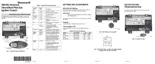
Fig. 4. S8610U in typical ST9120 application.
STARTUP AND CHECKOUT
Check out the gas control system:
• At initial installation of the appliance.
• As part of regular maintenance procedures.
• At maintenance intervals determined by the application.
• As the first step in troubleshooting.
• Any time work is done on the system.
Maintenance frequency must be determined individually
for each application; see Maintenance section.
A WARNING
FIRE OR EXPLOSION HAZARD
CAN CAUSE PROPERTY DAMAGE,
SEVERE INJURY, OR DEATH.
1. If you smell gas or suspect a gas leak, turn off
the gas at the manual service valve and
evacuate the building. Do not try to light any
appliance; do not touch any electrical switch
or telephone in the building until you are sure
no spilled gas remains.
2. Gas leak test must be done as described in
Steps 1 and 6 below during initial installation
and anytime work is done involving the gas
piping.
Step 1: Perform visual inspection.
a. With power off, make sure all wiring connections are
clean and tight.
b. Turn on the power to the appliance.
c. Open the manual shutoff valves in the gas line to the
appliance.
d. Test for gas leak before gas control if piping has been
disturbed.
Gas Leak Test:
Paint the gas control gasket edges and all pipe connec
tions downstream of the gas control, including the pilot
tubing connections, with a rich soap and water solution.
Bubbles indicate gas leaks. Tighten the joints and screws
or replace component to stop gas leak. Recheck with soap
and water solution.
Step 2: Verify control system ground.
The igniter, flame sensor, and ignition module must share
a common ground with the main burner. Use thermoplastic
insulated wire with a minimum rating of 105°C (221°F) for
the ground wire; asbestos insulation is not acceptable. If
the temperature at the wire could exceed 105°C (221°F),
use a shield to protect the wire from radiant heat gener
ated by the burner. Connect the ground wire as follows:
a. Fit one end of the ground wire with a female 1/4 in.
quick-connect terminal and connect it to the male
quick-connect GND (BURNER) terminal on the
ignition module.
b. Strip the other end of the wire and fasten it under the
igniter bracket mounting screw. If necessary, use a
shield to protect the ground wire from radiant heat.
c. The burner serves as the common grounding area. If
there is not good metal-to-metal contact between the
burner and ground, run a lead from the burner to
ground.
NOTE: Earth ground is not required.
69-0729—3 10

 Loading...