8 5895XL Manual - P/N 151142-L8:L 08/09/2017
Before You Begin Installing Earth Fault Resistance
* Regulated/special application when used for releasing.
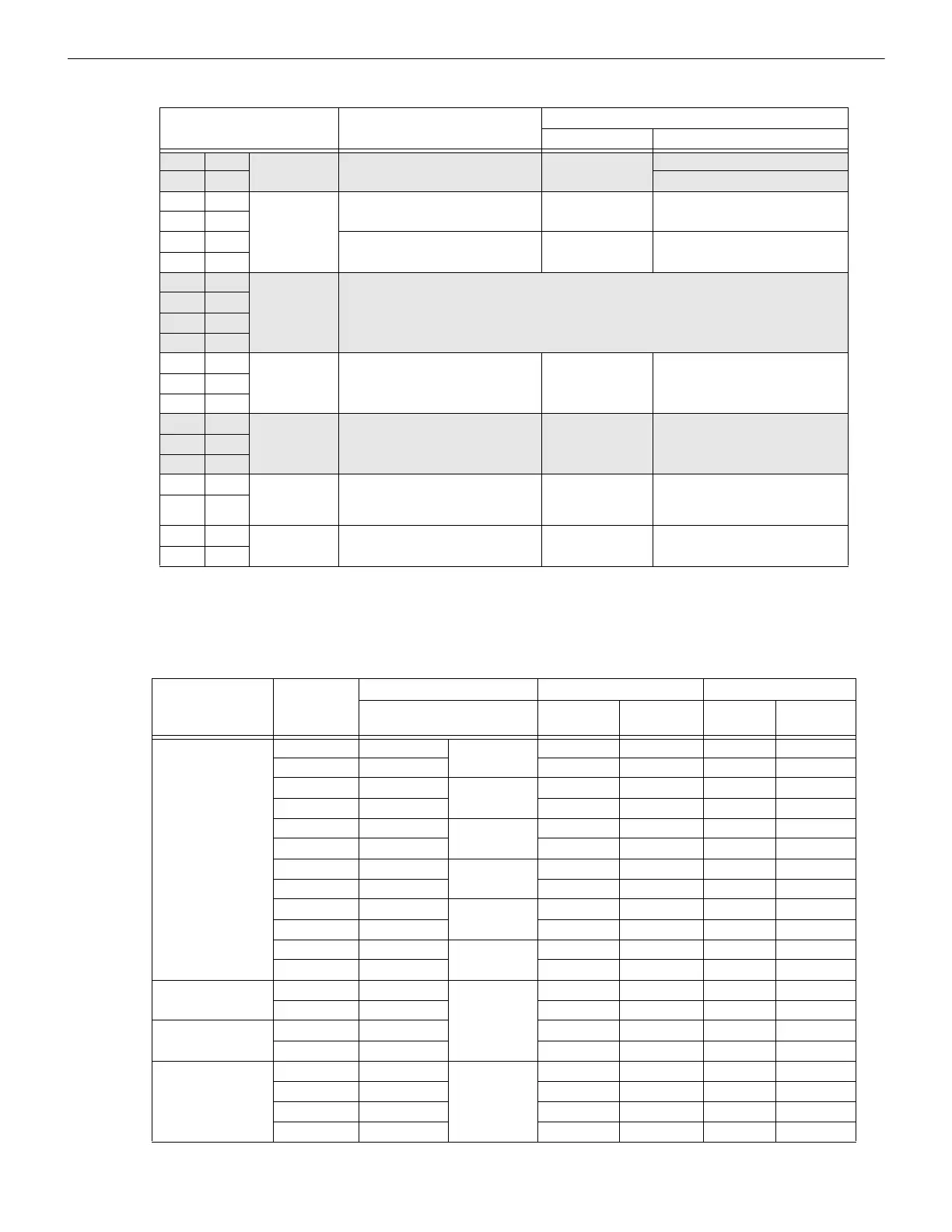
2.5 Earth Fault Resistance
Table 2.2 lists the earth fault resistance detection for each applicable terminal on the FACP.
14 X I/O 1* Flexput™ Circuit 24 VDC 3.0 A Notification Circuits
15 O 100 mA Initiation Circuits
16 B SBUS OUT SBUS communication 5 VDC 100 mA
17 A
18 + SBUS power 24 VDC 1.0 A
19 -
20 B SBUS IN Used for Class A installations
21 A
22 +
23 -
24 N.C. RELAY 2 General Purpose Relay 2 24 VDC 2.5 A
25 C
26 N.O.
27 N.C. RELAY 1 General Purpose Relay 1 24 VDC 2.5 A
28 C
29 N.O.
30 B SBUS IN/
OUT
5895XL communication with main
panel or to controlling 5895XL if
daisy-chained
5 VDC 100 mA
31 A
32 + MAIN 5895XL SBUS power (from
5820XL)
24 VDC 10 mA
33 -
Table 2.1 : Terminal Strip Description and Electrical Ratings
Terminal # and Label Description
Rating
Voltage Current
Table 2.2 : Earth Fault Resistance Values by Terminal
Function
Terminal
Number
Terminal Label Low Biased High Biased
(Values in kohms) High
Trip
High
Restore
Low
Trip
Low
Restore
Flexput™
Notification
Circuits
4 X I/O 6 - - 0 0
5O 00--
6 X I/O 5 - - 0 0
7O 00--
8 X I/O 4 - - 0 0
9O 00--
10 X I/O 3 - - 0 0
11 O 0 0 - -
12 X I/O 2 - - 0 0
13 O 0 0 - -
14 X I/O 1 - - 0 0
15 O 0 0 - -
SBUS
Communication
16 B SBUS OUT - - 0 0
17 A - - 0 0
SBUS Power 18 + 0 0 - -
19 - - - 0 0
Used for Class A
Installations
20 B SBUS IN - - 0 0
21 A - - 0 0
22 + 0 0 - -
23 - - - 0 0

 Loading...