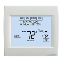
VISIONPRO
®
8000 WITH REDLINK™
133 68-0312—03
Typical wiring of a W7213/W7214 Economizer Module for a heat pump system, using a VisionPRO with RedLINK thermostat or
Equipment Interface Module.
Fig. 340. Wiring a W7213/W7214 Economizer Module for a heat pump system.
Typical wiring of a W7212 Economizer Module for a conventional heating system, using a VisionPRO with RedLINK thermostat or
Equipment Interface Module.
Fig. 341. Wiring a W7212 Economizer Module for a conventional heating system.
1“A” or “L/A” terminal must be configured for Economizer in the installer setup (ISU 222). These terminals are powered by the cool-
ing transformer (Rc terminal).
2Terminal AUX 2 is present only on the Equipment Interface Module.
3Add a normally closed relay as shown to make the W7213/W7214 Economizer Module compatible with the thermostat. The ther-
mostat energizes the "A" or "L/A" terminal during Occupied Periods.
120
VAC
Y1 Y2 AUX AUX 2 G
24
VAC
O OR B
N
3
4
1
2 & 5
TR1
TR
Rooftop Unit
Transformer
L/A Y Y2 AUX AUX 2 G
Thermostat/EIM
R
C
W7213/W7214 Economizer Module
(See wiring guidelines provided with the product)
O/B
O/B
1
3
2
MCR34809
3
1
120
VAC
Y1 Y2 W1 W2 G
24
VAC
N
3
4
1
2 & 5
TR1
TR
Rooftop Unit
Transformer
AYY2WW2G
Thermostat/EIM
R
C
W7212 Economizer Module
(See wiring guidelines provided with the product)
1
MCR34257A
 Loading...
