If using ST9420C to replace other Honeywell Programmers, the equivalent wiring terminations are shown in the tables below.
When converting a fully wired system, remove the wired room thermostat and its associated electrical wiring. Some minor changes are required at the
10-way junction box. These are described in the table below and shown on the wiring diagrams on page 4.
ST6300/ST6400/ST9400 N L 1 2 3 4
ST9420C N L 1 2 3 4
ST699/ST799 N L 3 4 5 6 7 8
ST9420C N L 4 2 not connected 3 1 not connected
ST7100 N L 3 4 5 6 7 8
ST9420C N L not connected 2 4 not connected 1 3
ST9420C Programmers will mount directly onto many existing manufacturers’ back-plates, with a minimal need for re-wiring. They are also supplied
complete with a wiring back-plate, should this not be the case.
Refer to Honeywell Technical Help Desk for wiring conversion diagrams.
Check the unit powers up correctly and that the display does not remain blank.
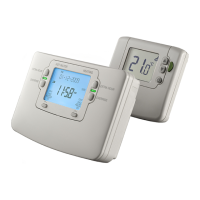
ST9420C must be powered up before DT92E is installed, so that the signal strength tests can be conducted.
The initial signal strength test will verify that both units have each others addresses in their memory, and can therefore communicate. The process of
writing respective addresses into memory is called BINDING.
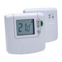
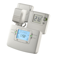
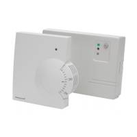
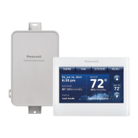
1.8 Replacing Other Manufacturers’ Time Controls
1.9 Powering Up ST9420C
1.7 Replacement Wiring
Remove links Add links
S-Plan
Add wire link from terminal 4 to terminal 5
Y-Plan
Add wire link from terminal 4 to terminal 5
C-Plan
Remove wire link from terminal 5 to terminal 9 Add wire link from terminal 4 to terminal 9
W-Plan
Add wire link from terminal 4 to terminal 7
 Loading...