Ed.03/2009
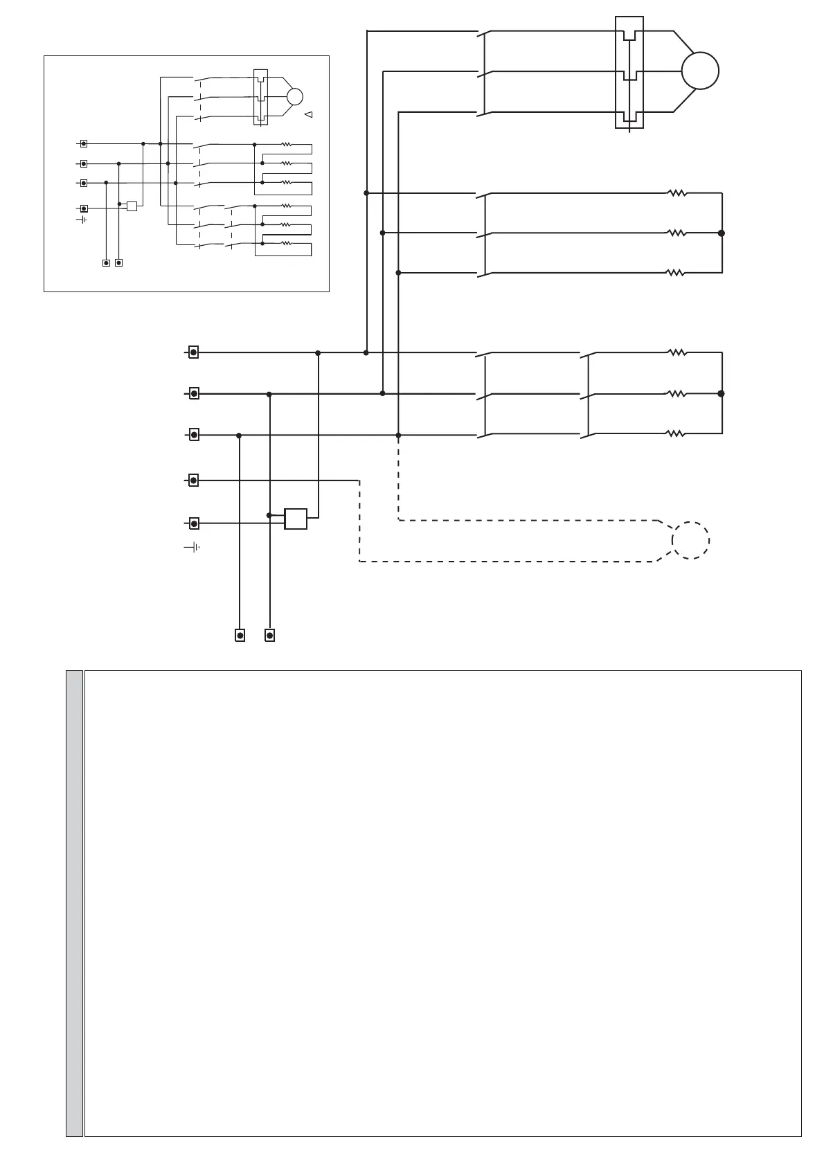
400V3N ~ 50/60HZ
FA = Filtro Antidisturbo - Electromagnetic Field Filter
C1 = Teleruttore pompa lavaggio - Remote Switch for wash pump
C2 = Teleruttore resistenza vasca - Remote Control Switch for tank heating element
C3 = Teleruttore resistenza Boiler - Safety Remote Control Switch for boiler heating element
C4 = Teleruttore sicurezza - Safety Remote Switch
PT1 = Termica elettropompa - Electropumpe thermal protection
PLAV1 = Motore Pompa Lavaggio - Wash Pump
RB = Resistenza Boiler - Boiler heating element
RV = Resistenza vasca - Tank heating element
P
R
= Pompa Pressione
- Pump Pression
PS = Pompa Scarico (optional) - Drain Pump (optional)
DD = Dosatore Detersivo - Detergent Pump
MD = Motore pompa detersivo (optional) - Detergent pump motor (optional)
MP1 = Microinterruttore porta - Door microswitch
MP2 = Predisposizione doppio microinterruttore porta - Predisposition double door microswitch
TS = Termostato sicurezza boiler - Boiler Safety thermostat
F,F1,FA1 = Fusibile - Fuse
IL = Interruttore generale macchina - Line selector
ST = Pulsante Avvio Ciclo - START button
SD = Pulsante selezione Temperatura Boiler/Vasca (decrementa)
Boiler/Tank temperature selection button (decrease)
SI = Pulsante selezione Ciclo/Avviamento Automatico-Manuale (incrementa)
Cycle/Automatic or Manual Start (increase)
LC1 = Lampada Ciclo Corto - Short cycle light
LC2 = Lampada Ciclo Medio - Medium cycle light
LC3 = Lampada Ciclo Lungo - Long cycle light
LC4 = Lampada Ciclo Intensivo - Intensive cycle light
EVRIS = Elettrovalvola risciacquo e carico acqua - Rinse and water inlet electrovalve
STB = Sonda temperatura boiler - Boiler temperature probe
STV = Sonda temperatura vasca - Tank temperature probe
PRV = Pressostato vasca - Tank pressostat
PRB = Pressostato boiler - Boiler pressostat
SCHEMA DI POTENZA / DIAGRAM POWER CAP 10E BT-CAP 12 E BT
LEGENDA - LEGEND
C2
C1
9000 W
C3
C4
1
2
3
4
5
6
1
2
3
4
5
6
1
2
3
4
5
6
1
2
3
4
5
6
PT1
M
3~
4000 W
1100 W
N
400V 3N ~ 50Hz
L1 L2 L3
PE
230V~50Hz
FA
L2
L1
PS
Pompa scarico
Drain pump
100 W
M
~
RB
RV
PLAV1
RB
RB RB
RV
RV
RV
230V3 ~ 50/60HZ
M
230 V3~ 50 Hz
PT1
C2
1
2
3
4
5
6
C4
1
2
3
4
5
6
L1 L2
C1
1
2
3
4
5
6
RB
RB
RB
L1
L2
230 V~ 50 Hz
FA
C3
1
2
3
4
5
6
RV
RV RV
230 V3 ~ 50Hz
3~
L3
PE