EasyManua.ls Logo

Horizon Fitness APC-61 User Manual

Horizon Fitness APC-61
136 pages
To Next Page IconTo Next Page
Page #1 background imageLoading...
Page #1 background image
A
PC-61 Revision Control List
Manual No. Date Bulletin Code S/N applied History
Page
US504004-00 Jan/17/2001 (First Edition)
1.Correcting the description of "2-11 Hydraulic Pressure Does not Operate." 2-20
2.Correcting the Hydraulic Circuit to (For S/N 100001 to 122899) and (For S/N
123001 or above). 5-3.4
US504004-01 Jun/4/2001 1.Adding precautions on P.C.board and ROM IV
2.Adding the relay in the control bo
x
6-4
3.Correcting producers No. for the rlay 7-8
4.Correcting wiring diagrams 7-6, 7-10, 7-11
US504004-03 Feb/27/2008 1. Adding the 61II-related pages.
2. Correcting the term "cut knife" to the "cutting knife".
All Page
3. Correcting the term "back gauge" to the "backgauge".
All Page
1
-
9
,
1
-
10
,
1
-
11
,
2
-
23,2-24,2-25,2-
26,2-27,2-28,3-
16,3-17,6-5,6-6,6-
7,6-8,6-9,7-14,7-
15,7-16,7-17,7-
18,7-19

Table of Contents

Question and Answer IconNeed help?

Do you have a question about the Horizon Fitness APC-61 and is the answer not in the manual?

Horizon Fitness APC-61 Specifications

General IconGeneral
BrandHorizon Fitness
ModelAPC-61
CategoryPaper Cutters
LanguageEnglish

Summary

Necessary Tools for Maintenance and Repair

Abbreviations in This Manual

Wire Color Abbreviations

Lists abbreviations used for wire colors within the manual.

Electronic and Electrical Parts Abbreviations

Lists abbreviations for electronic and electrical components.

Machine Parts Descriptions

1-1 General View

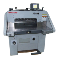
Provides an overall view of the machine's main components and their labels.

1-2 Operation Panel Descriptions (T61)

Details the controls and indicators on the T61 operation panel.

1-5 Entering Service Screen (61II)

Explains how to access and navigate the service screen for model 61II.

Troubleshooting

2-1 U blinks on the Display (Backgauge Does Not Operate)

Addresses issues where the display shows 'U' and the backgauge is unresponsive.

Adjustment

3-1 Fine Adjustment of Cut Size

Describes the procedure for fine-tuning cut size with 0.1mm variations.

3-4 Adjustment of Electromagnetic Brake Gap

Details the process for adjusting the electromagnetic brake gap.

3-7 Adjustment of Knife Lower Limit Position

Explains how to adjust the knife's lower limit position.

Repair

4-1 Replacing Knife Holder

Provides step-by-step instructions for replacing the knife holder component.

4-2 Replacing Clamp

Details the procedure for replacing the clamp assembly.

4-11 Replacing Encoder

Explains how to replace the encoder unit.

Hydraulic Parts

5-1 Hydraulic Parts Description

Describes the hydraulic components for serial numbers 100001 and above.

5-2 Hydraulic Circuit

Presents the hydraulic circuit diagram for specific serial number ranges.

Electrical Parts Description

6-1 Identification and Location of Motors and Encoder

Identifies and locates motors and the encoder on the machine.

6-3 Identification and Location of Components in the Control Box

Details components found within the main control box.

6-5 Panel Internal Layout and Name (61II)

Shows the internal layout and names of parts on the 61II panel.

System Wiring and Connections

7-1 Board Connections

Illustrates the connections between the various circuit boards.

7-2 CPU Board (QPW-162)

Details the CPU board and its connections.

7-4 Control Board (QPW-153D), LED and Main Parts

Describes the control board, its LEDs, and key components.

Related product manuals