PAGE 2 08 JUN 2005 MAN0508-03
2.2 Mounting Instructions (Back Plane / DIN-Rail)
There are two ways to mount the FOX104 / FOX404 in a panel box. It can either be hard-mounted to the
back plane or mounted on a DIN-Rail strip.
a. Back Plane Mounting
1. Read the Installation Chapter in the hardware manual of the controller you are using prior
to
mounting the FOX104 / FOX404. Observe requirements for the panel layout design and
adequate clearances. A checklist is provided for your convenience in the hardware manual. (See
the Additional References section in this document.)
2. Drill holes. (Refer to Figure 2.)
3 Install and tighten washers and nuts. Do not
over-tighten.
4. Connect the communications and power cables to the FOX104 / FOX404 ports using the
provided connectors.
5. Install up to four SmartStack Modules on the FOX104 / FOX404.
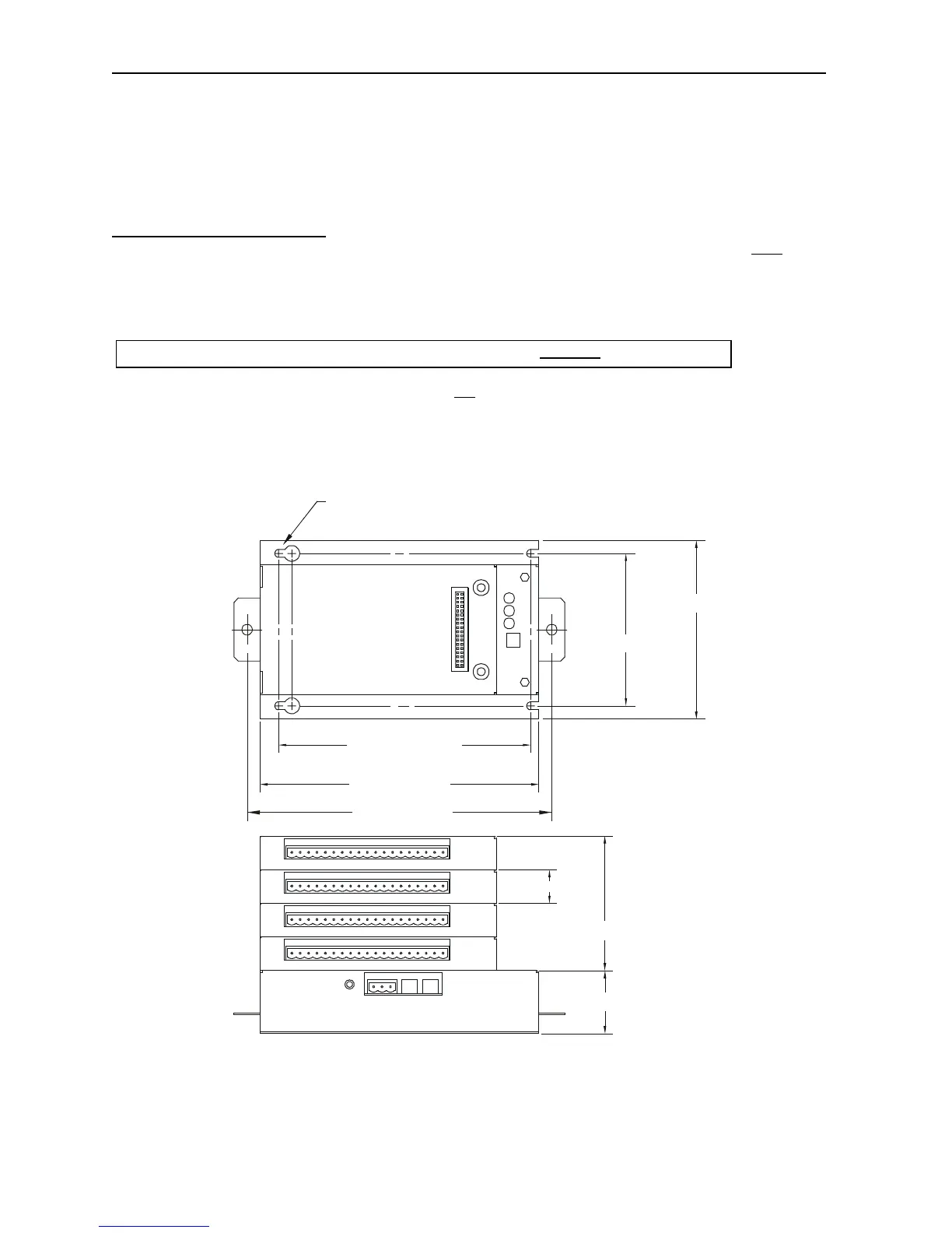
2.3 Dimensions and Hole Pattern
Figure 2 – FOX104/404 Hole Pattern (Top) and Viewed with 4 SmartStack I/O Modules (Bottom)
NOTE: Use #8-32 or M4 mounting hardware consisting of four pan head screws with external tooth lock washers.
6.000 [152.40mm]
6.63 [168.3mm]
3.625 [92.08mm]
4.25 [108.0mm]
MOUNTING HOLES FOR #8 OR M4 HARDWARE
1.50 [38.1mm]
3.20 [81.3mm]
0.80 [20.3mm]
001FOX001-R1
7.87 [200.0mm]
Warning: Make sure the power and network connectors are removed from the FOX.
 Loading...