Do you have a question about the Hoshizaki DCM-240BAE and is the answer not in the manual?
Main structural frame for the ice dispenser.
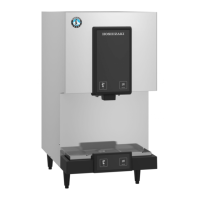
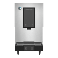
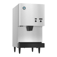
The main body or housing of the unit.
Power cord for the unit.
Leg for adjusting height and leveling.
Main front panel of the unit.
Primary frame component.
Secondary frame component.
Motor driving the ice making mechanism.
Screw mechanism for moving ice.
Assembly controlling ice dispensing.
High-strength screw for assembly.
Main component of the refrigeration system.
Heat exchanger for cooling.
Controls refrigerant flow.
Valve for accessing the circuit.
Controls water flow.
Tank for holding water.
Detects water level.
Tubing for water supply.
Main electrical control enclosure.
Steps down voltage for controls.
Protects electrical circuits.
Electrical switch controlled by a signal.
Secondary electrical control enclosure.
Capacitor for motor starting/running.
Capacitor for motor starting.
Component to start motor operation.
Main front panel with controls.
On/Off switch.
Indicator light.
Push-button switch.
Document with operating instructions.
Label indicating the model number.
Label with product specifications.
Mounting bracket for solenoid.
Electromechanical actuator.
Shutter plate component.
Fastener for assembly.
Top cover for the ice bin.
Small electrical switch.
Plate for balancing.
Motor driving the fan.
Rotating component for airflow.
Elastic fitting for vibration damping.
Fastener for assembly.
User guide for the product.
Replacement fuse for protection.
| Storage Capacity | 80 lbs |
|---|---|
| Refrigerant | R-404A |
| Production Capacity | 240 lbs per day |
| Power Supply | 115V/60Hz/1Ph |
| Installation | Freestanding |
| Water Supply | 3/8" FPT |