Do you have a question about the Hoshizaki IM-240NE/WNE and is the answer not in the manual?
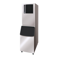
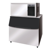
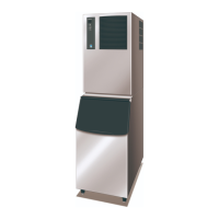
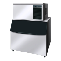
Detailed specifications and dimensions for various Hoshizaki ice maker models.
Explains the main components and their locations within the ice maker units.
Information and notes regarding the controller board and its handling.
Step-by-step guide for starting the icemaker operation.
Details on the bin control switch, its function, and assembly.
Guidelines for routine cleaning of the machine, bin, scoop, and handle.
Diagrams illustrating the water and refrigerant flow paths in different models.
Tables detailing ice production, cycle times, and consumption under different conditions.
List of error codes, their descriptions, operations, and reset procedures.
Troubleshooting guide for common problems without specific error codes.
Instructions for adjusting the expansion valve setting for optimal ice production.
Service information, leak treatment, and handling for refrigerant lines.
Step-by-step guide for removing and replacing the compressor unit.
Instructions for removing and replacing the expansion valve.
Guide for removing and installing the actuator motor.
Steps for replacing the controller board.