3.1 ALIGNMENT OF COMPRESSOR COUPLINGS (Continued)
If the gap is checked with the couplings “hard together”, ie, in the normal running condition, it should
be equal to the required coupling gap: 3.175mm (0.125”).
NOTE: If a “limited float” coupling is used with an electric motor whose shaft has no thrust bearing,
the gap must be correct with the motor shaft on its magnetic centre. In this instance the
facial alignment check should be made, rotating the driven half coupling only as the drive
(motor) half coupling is not located axially, or preferably by a “double-clock” method, which
avoids the problem of repeated axial position.
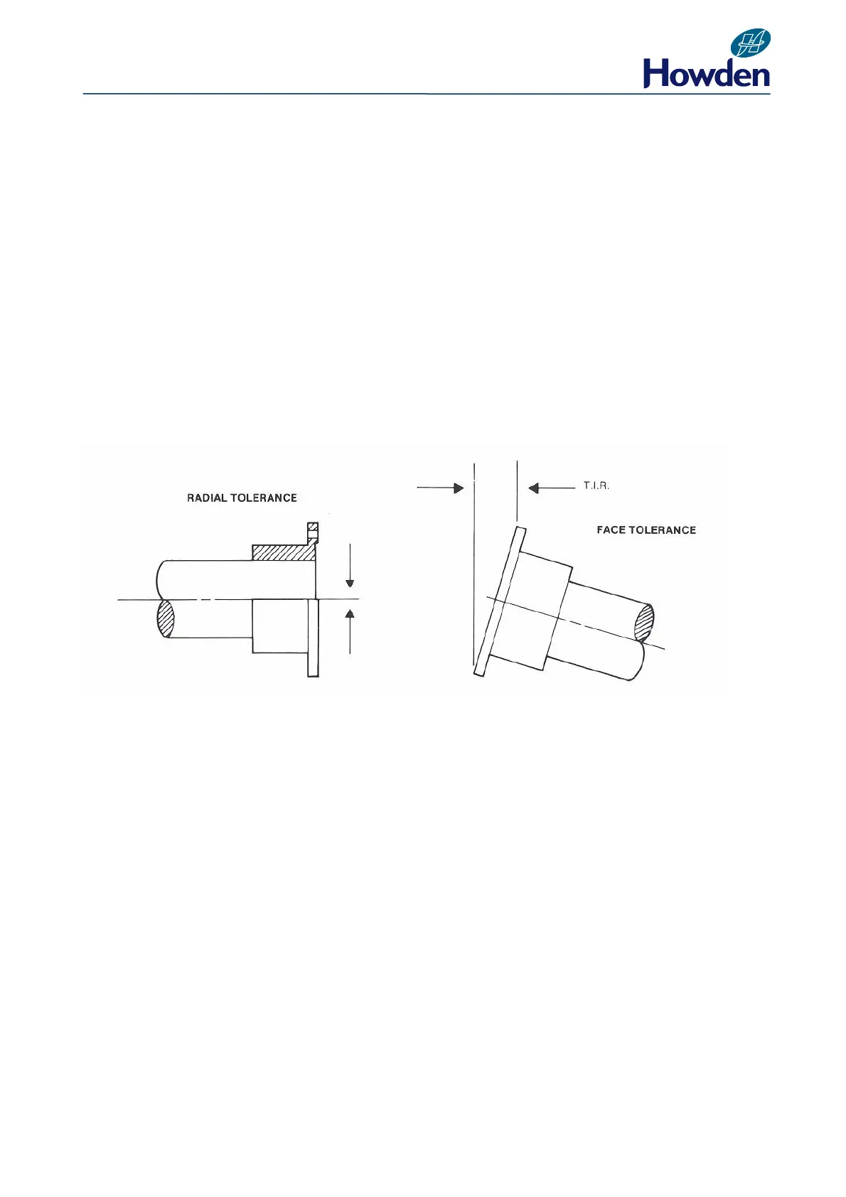
3.2 ALIGNMENT TOLERANCE
The maximum acceptable line-up tolerance for couplings on compressor installations is as follows:
RADIAL TOLERANCE FACE TOLERANCE
Application
A. Motor to Gearbox or Compressor ie couplings operating up to 3,600 rpm
Radial Tolerance Face Tolerance
0.15mm (0.006”) TIR TIR 0.005mm/cm or 0.005”/in Dia. Of coupling
B. Gearbox to Compressor i.e. couplings operating above 3,600 rpm
Radial Tolerance Face Tolerance
0.10mm (0.004”) TIR TIR 0.005mm/cm or 0.005”/inch Dia. Of coupling
Radial Tolerance
Eccentricity = ½ TIR on circumference
TIR denotes Total Indicator Reading obtained by Clockgauge