7.5 RE-ASSEMBLY AFTER ANNUAL INSPECTION
When all checks and corrections have been made, and assuming no major problems have
developed, the compressor can be re-assembled. (Refer to the Sectional Arrangement drawing
supplied and torque specifications as advised under Section 9.1)
WRV163 Compressor
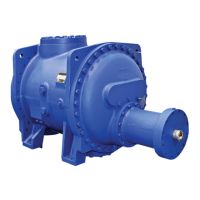
Ensure the guide block is in position in the slide valve bore, insert the slide valve and push it all the
way to the ‘on load’ position (Fig. 24).
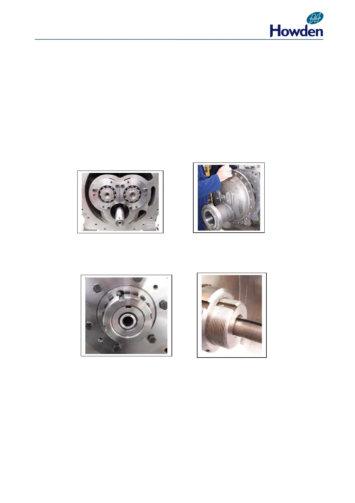
Insert an eyebolt into the outlet end cover flange and with the aid of suitable lifting equipment re-
assemble the outlet end cover/hydraulic cylinder (Fig. 25).
Secure with set pins to the main casing. Remove the lifting sling and eyebolt.
Fig. 24 Fig. 25
Refit the piston into place in the hydraulic cylinder. Secure with new lockwasher and locknut (Fig.
26). Replace the actuator stop sleeve. Fit the cylinder end cover, taking care to ensure the dowel is
properly located in the spiral groove of the indicator spindle (Fig. 27).
Fig. 26 Fig. 27
Secure the cover with cap screws. Ensure the limit switches are in position securely fastened,
assemble the limit switch cover, if fitted, and secure with cap screws.
For compressors fitted with LPI sensors, refit the cylinder end cover and secure the cover with
capscrews. Refit and secure the LPI sensor.