8.2 DISMANTLING 163 COMPRESSOR FOR MAJOR OVERHAUL (Continued)
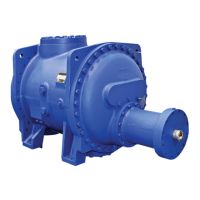
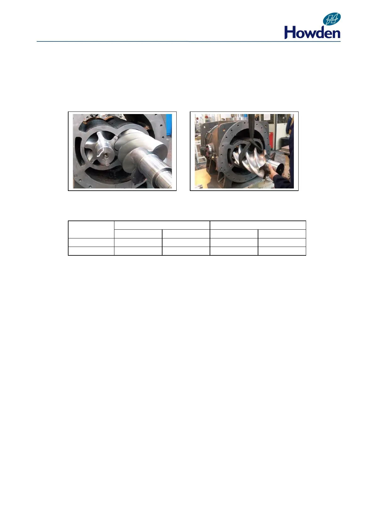
Removing the Rotors (163mm)
Now that the inlet and outlet end casings and the thrust bearings have been removed as described
previously, the rotors can be withdrawn from the main casing as shown in Figs.46-47. See table Fig.
48 for estimated rotor weight.
Fig. 46 Fig. 47
ESTIMATED WEIGHTS OF ROTORS
Fig. 48
The journal bearings can now be extracted from the Main and Inlet casings using an extractor tool.
See Tool List Section 9.3.
Fit new journal bearings using assembly tool in preparation for re-assembly.
The journal bearings are located by a dowel pin and are retained by circlips.
8.3 RE-ASSEMBLY 163 COMPRESSOR AFTER OVERHAUL
When repair or rectification work has been completed the compressor should be assembled as
follows.
1. Lubricate the bearing bores with lubricating oil and lift in the rotors, ensure the lobes mesh at the
serial numbers on the rotors.
2. Assemble the inlet casing to the main casing, locate with the dowel pins, and secure with set
pins. (See Torque Specification in Section 9.1)
3. Locate the thrust bearing adjustment plates over the rotor shafts at the outlet end and slide them
into position. Heat the angular contact thrust bearings using an oil bath or induction heater to a
temperature of approx 100°C and assemble to the rotors.
4. Prior to wire locking the thrust retaining plate in place, it is necessary to check that the rotor
outlet end clearance is correct.
5. Fit lockwasher/locknut and secure (Fig. 36).