8.5 RE-ASSEMBLY WRVi255, WRVi321 & WRVi365 COMPRESSORS AFTER OVERHAUL
(Continued)
Checking Rotor Outlet End Clearance
Insert the jacking screw into the holes provided on the bearing housing flange and lightly tighten the
jacking screws until resistance is felt.
The action of tightening the jacking screws draws the rotors against the outlet face of the main
casing. Ensure the adjusting pieces are located between the flange of the thrust sleeve and main
casing. (Fig 71)
Set up a dial indicator on a convenient part of the main casing with the indicator spindle touching on
the end of the rotor. Remove the tension from the jacking screws and ease them back a few
threads. Set the dial indicator to zero.
Apply the torque wrench to the set screw securing the thrust bearing housing to the main casing and
tighten the screws to the specified torque value (used in Section 9.1).
NOTE: The movement shown on the indicator dial is the rotor outlet end clearance. Check it
against the table, Fig. 70.
Fig. 70 Rotor to Main Casing Outlet End Clearance
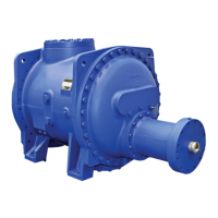
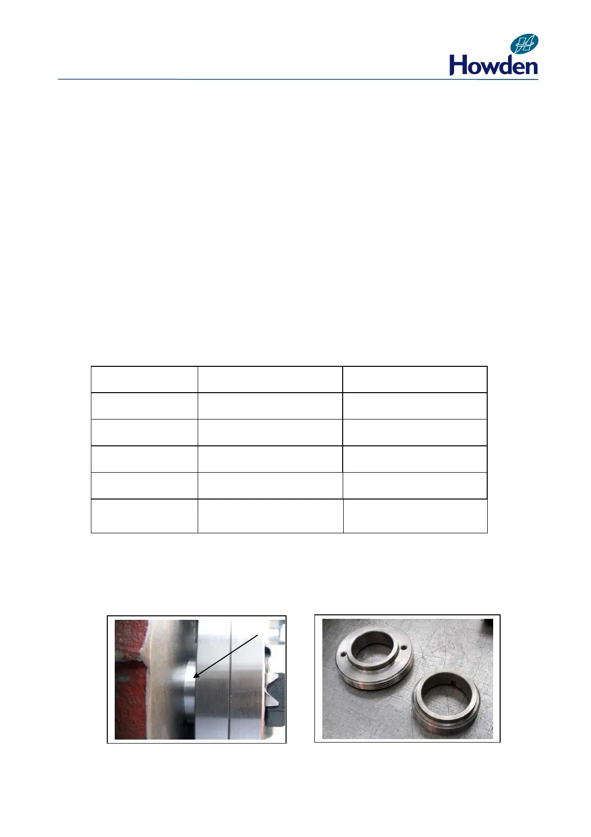
Adjustment, if necessary, is carried out by machining of the adjusting washers behind the thrust
bearing sleeve (WRVi255, WRVi321 & WRVi365) (Fig. 71).
WRV204 Compressor rotor outlet end clearance is carried out by grinding the balance pistons
(Fig 72 ) .
Fig. 71 Fig. 72
Rotor Outlet End
Clearance
Maximum Allowable
Clearance
0.002”/0.003”
(0.050/0.075mm)
0.003”/0.004”
(0.075.0.100mm)
0.008”/0.010”
(0.200/0.250mm)
0.012”/0.014”
(0.300/0.350mm)
0.012”/0.014”
(0.300/0.350mm)