Hoyles Electronic Developments Ltd
Sandwash Close, Rainford, St Helens, WA11 8LY, UK
www.hoyles.com
sales@hoyles.com
+ 44 (0) 1744 886600
Output resistors
The two outputs OP1 and OP2 both have two sets of resistor combinations selectable by the four jumpers, J1, J2, J3 and J4 on
the PCB. With all four jumpers in position A, the alarm resistor is 1K and the EoL resistor is also 1k for both OP1 and OP2. With all
four jumpers in position B, the alarm resistor is 4K7 and the EoL resistor is 2k2 for both OP1 and OP2.
Other resistor combinations to suit other intruder panels are available on request.
Alarm Tones
The EX125iS-HX has two selectable alarm tones available, a high powered tone and a low powered tone. The required tone can
be selected by switching the TONE switch on the PCB into either the HI or LO position.
Power requirements - A continuous supply of 12vdc is required, 15mA max quiescent and 150mA max in alarm.
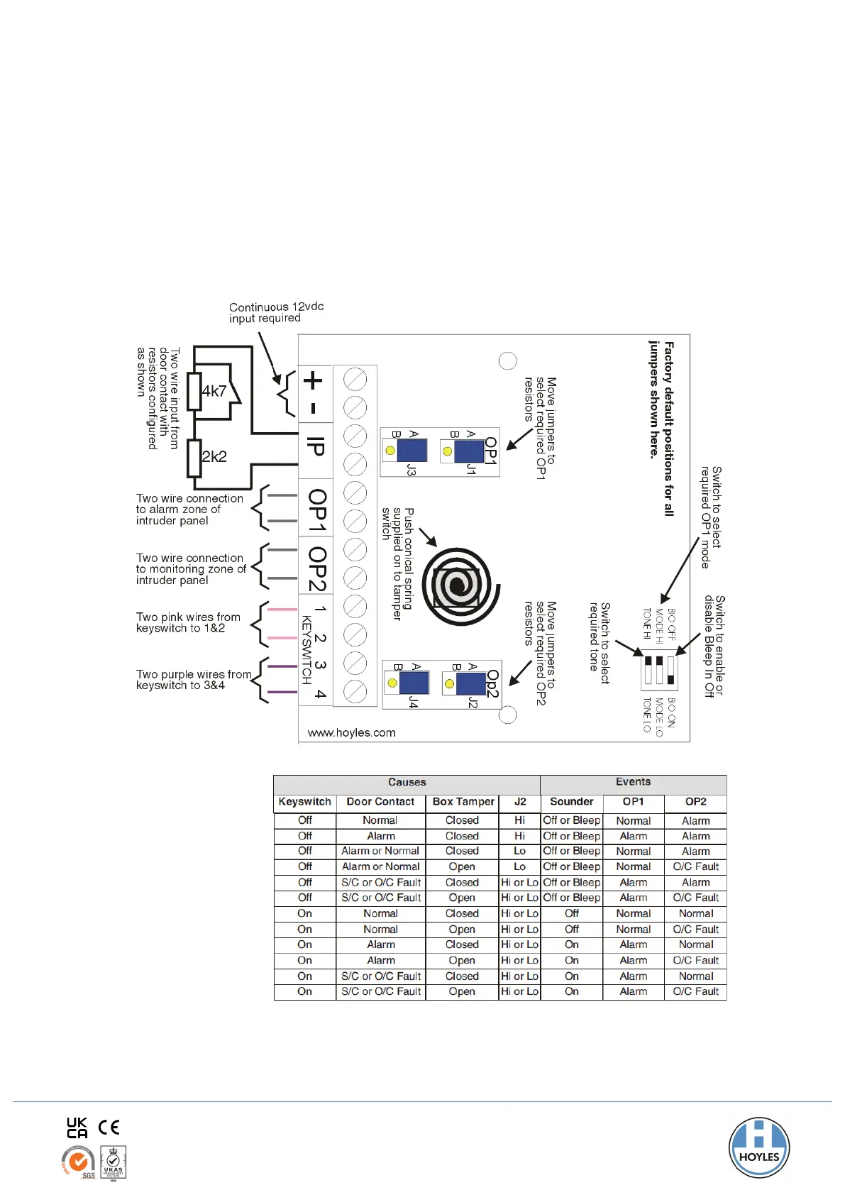
Connection Details
Cause and Event Table
The table shows the
possible events based
on the available causes.
Note: When jumpers for OP1 and OP2 are all set in position A, Normal = 1k and Alarm = 2k (1k+1k)
When jumpers for OP1 and OP2 are all set in position B, Normal = 2k2 and Alarm = 6k9 (2k2+4k7)
 Loading...