Model 339A
Section
II
SECTION
II
INSTALLATION
2-1. INTRODUCTION.
2-2. This section
of the manual
contains
information
and
instructions
necessary to
install
the Model
339A
Distortion
Measurement Set. Also included are
initial
inspection
procedures,
power
and grounding require-
ments,
environmental
information,
and packaging
instructions.
2-3.
INITIAL
INSPECTION.
2-4.
This
instrument was
carefully
inspected, both
mechanically
and
electrically, before
shipment.
It should
be
free of
mars and
scratches
and
in perfect electrical
ordep. The
instrument should be
inspected upon receipt
for
damage
that might
have occured in transit. If the
shipping
container or
cushioning material
is
damaged, it
should
be kept until
the contents of the shipment have
been
checked for
completeness and the instrument has
been mechanically and
electrically
inspected.
Procedures
for testing the electrical
performance of the Model
339A
are
given
in
Section IV of this manual. If
the
contents are
incomplete,
if
there
is
mechanical damage or defect, or
if
the
instrument
does not
pass
the Performance Tests,
notify the nearest Hewlett-Packard
Office.
(A
list
of
the-
hp-
Sales and Service Offices is
presented at the
back of
this
manual.)
If the shipping container is damaged,
or
the
cushioning
material shows
signs of stress, notify
the
carrier as well
as
the Hewlett-Packard Office. Save the
shipping
materials for the carriers
inspection.
2-5.
PREPARATION
FOR
USE.
2-6.
Power
Requirements.
2-7.
The Model
339A
requires
a
power
source of 100.
120, 220,
or
240
V
ac
(+5%
-
10%),
48
Hz
to 66 Hz single
phase.
Maximum power consumption
is
48 VA.
2-8.
Line
Voltage
Selection.
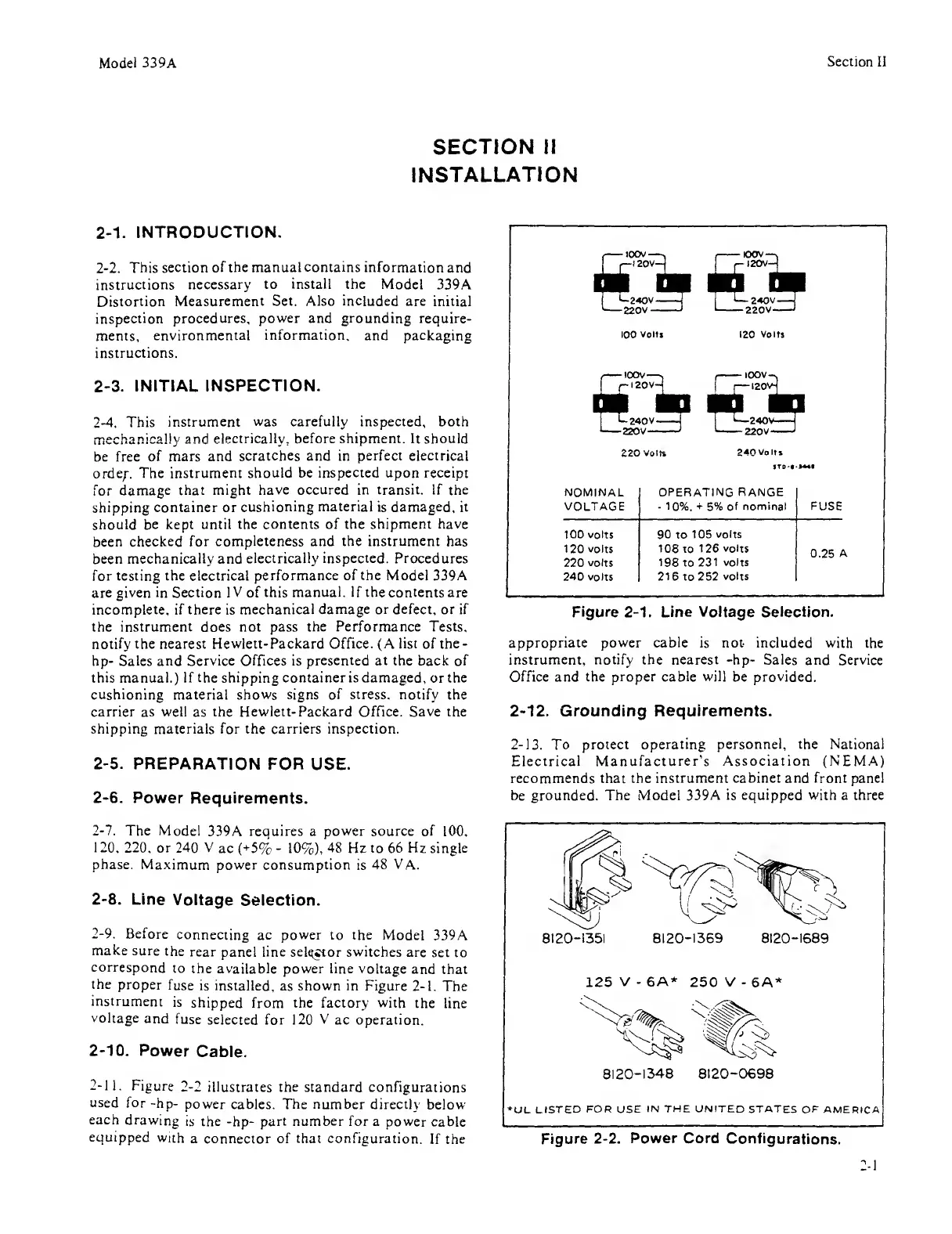
2-9.
Before
connecting ac power to the
Model 339A
make
sure
the
rear panel line
selector
switches
are
set to
correspond
to
the available power line voltage
and
that
the
proper
fuse
is
installed, as
shown in
Figure
2-1.
The
instrument
is
shipped from the factory with
the line
voltage
and
fuse
selected for 120
V
ac operation.
2-10.
Power
Cable.
2-11.
Figure 2-2
illustrates the
standard configurations
used for
-hp-
power
cables.
The number
directly below
each
drawing
is the
-hp-
part
number
for a power
cable
equipped
with
a connector of
that
configuration.
If
the
100
Volt!
IZO
Volts
NOMINAL OPERATING RANGE
VOLTAGE
-
10%.
+
5% of
nominal FUSE
100 volts 90 to
105 volts
120 volts 108 to
126 volts
0.25
A
220
volts 198 to
231 volts
240
volts
216 to 252
volts
Figure
2-1.
Line Voltage
Selection.
appropriate
power
cable is not included with
the
instrument, notify the nearest -hp-
Sales and Service
Office and the
proper cable will
be provided.
2-12.
Grounding Requirements.
2-13.
To protect
operating personnel, the National
Electrical
Manufacturer's Association (NEMA)
recommends that the
instrument cabinet and front panel
be grounded. The Model
339A is equipped with a three
Figure
2-2.
Power Cord
Configurations.

 Loading...

