Section IV
Model
339A
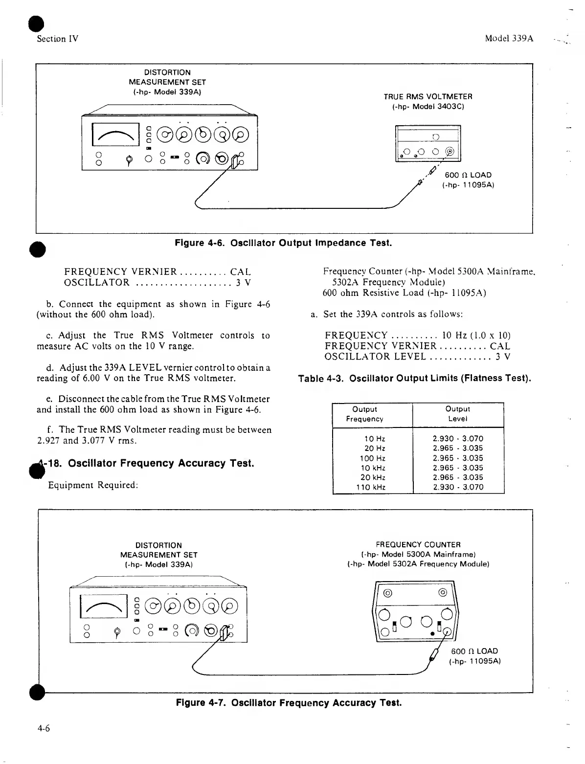
DISTORTION
MEASUREMENT
SET
(-hp- Model 339A)
TRUE
RMS VOLTMETER
(-hp- Model 3403C)
Figure
4-6.
Oscillator Output
Impedance Test.
FREQUENCY
VERNIER
CAL
OSCILLATOR
3
V
b. Connect the equipment as shown
in Figure
4-6
(without the
600
ohm load).
c.
Adjust the True RMS
Voltmeter
controls
to
measure AC
volts on the 10
V
range.
d.
Adjust the 339
A
LEVEL vernier control to obtain
a
reading of
6.00
V
on
the True
RMS voltmeter.
Frequency
Counter (-hp-
Model 5300A
Mainframe.
5302A Frequency Module)
600
ohm Resistive Load (-hp- 1
1095A)
a. Set
the
339A
controls as follows:
FREQUENCY 10 Hz (1.0
x
10)
FREQUENCY
VERNIER
CAL
OSCILLATOR LEVEL
3
V
Table
4-3. Oscillator
Output Limits (Flatness Test).
e. Disconnect the cable from the True
RMS Voltmeter
and install the 600
ohm load
as
shown
in Figure
4-6.
f.
The True RMS Voltmeter reading must
be between
2.927 and
3.077
V
rms.
1-1
8.
Oscillator Frequency Accuracy Test.
Equipment
Required:
DISTORTION
MEASUREMENT SET
(
hp- Model
339A)
FREQUENCY
COUNTER
(-hp- Model
5300A Mainframe)
-hp- Model 5302A Frequency
Module)
iUB°
°j2
600
fl
LOAD
(-hp-
1
1095A)
Figure
4-7.
Oscillator Frequency
Accuracy
Test.
4-6