Model
339A
Section
VII
SECTION VII
MANUAL
CHANGES
7
1. INTRODUCTION.
7-6.
MANUAL
CHANGE
INSTRUCTIONS.
7-2.
This
section
contains
information
necessary to
adapt this
manual to
instruments
with
serial
numbers
lower than the
number listed
on the title
page.
7-3.
MANUAL
CHANGES.
7-4.
To adapt
this manual to your instrument, refer
to
le
7-1
and
make the manual changes listed
opposite
ur instrument serial number. These changes
should
be
performed in
the sequence listed.
7-5.
If
your instrument serial number is
not listed
on
the title
page
of this manual or in
Table 7-1,
it may be
documented
in
a
yellow MANUAL
CHANGES
supple-
ment included
with
the manual.
For
additional
informa-
tion, refer to INSTRUMENT
AND MANUAL
IDEN-
TIFICATION in Section
I.
CHANGE
A
The
oscillator circuitry
was simplified
beginning
with in-
strument
serial
number
1730A00266. To
adapt this
manual to
prior
instruments make the
following
changes.
Page 6-3,
Table
6-3.
Add:
A1C20,
0180-0291, Cap-Fxd
1
jx F
±
10%
35
VDC
TA
A1CR1,
1901-0518,
Diode-Schottky
A1Q1,
1855-0360,
Transistor
Mosfet N-Chan
D-Mode
A1R32, R33,
0698-7332, Resistor
1 M 1% .125
W
F
TC
=
0±
100
Delete:
A1CR14,
1901-0040,
Diode-Switching 30
V
5
mA
Table
7-1.
Manual
Changes by
Serial Number.
Instrument Serial No.
Make
Manual
Change
1 730A001 01
to
1 730A00266
A
Page
8-21/8-22,
Figure
8-17.
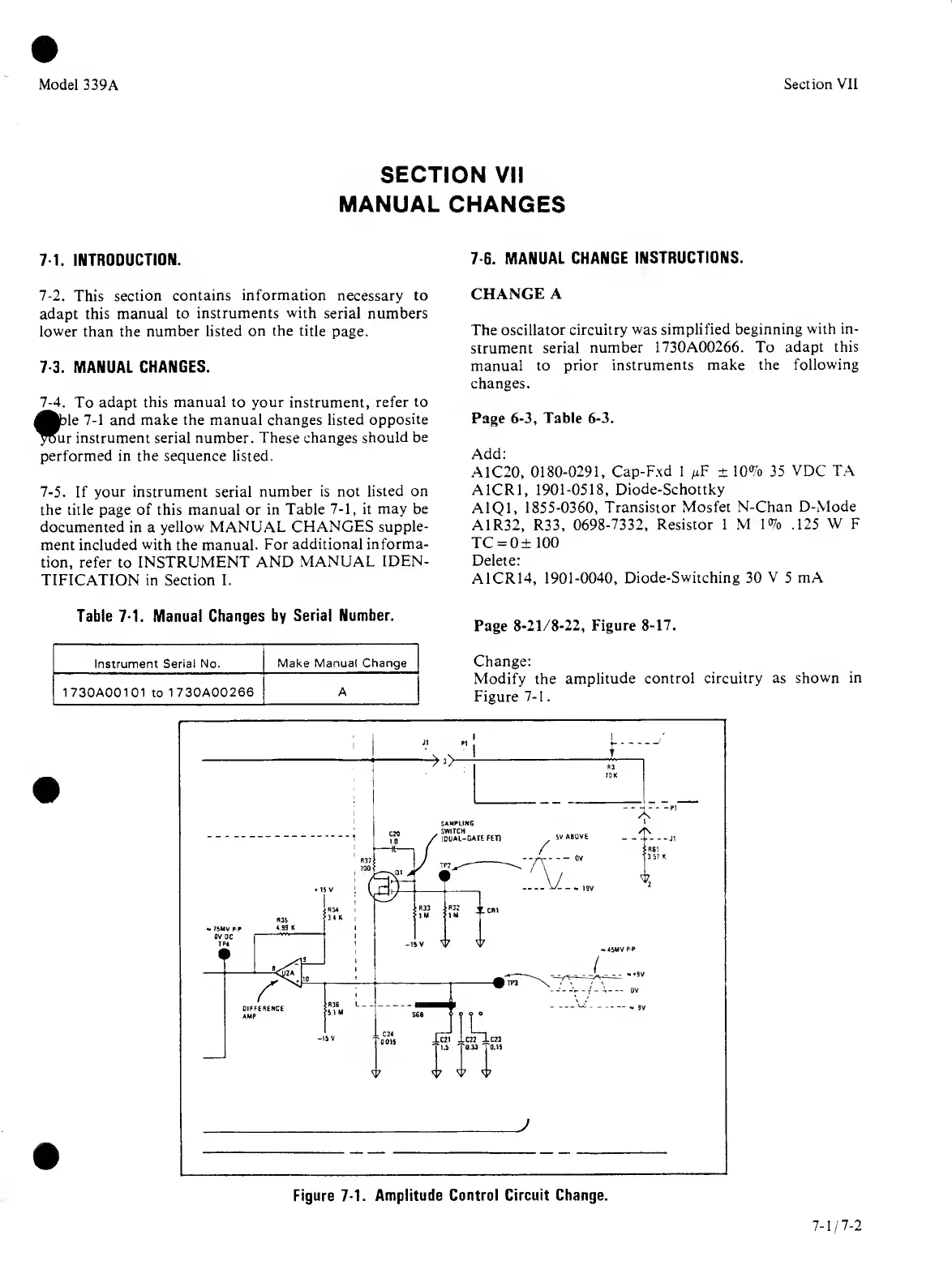
Change:
Modify the
amplitude
control circuitry as
shown in
Figure
7-1.
Figure
7-1.
Amplitude Control Circuit Change.