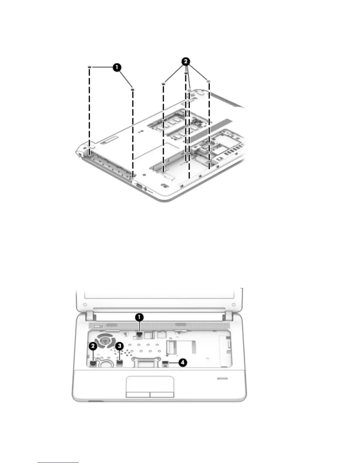
6. Remove the four Phillips PM2.0×2.0 broad head screws (2) in the hard drive bay that secure the top
cover to the base enclosure.
7. Turn the computer right side up with the front toward you.
8. Open the computer as far as it will open.
9. Disconnect the following cables from the system board:
(1) Power button board ZIF connector and ribbon cable
(2) Card reader board ZIF connector and ribbon cable
(3) TouchPad button board ZIF connector and ribbon cable
(4) Fingerprint reader module ZIF connector and ribbon cable
10. Separate the rear edge of the top cover (1) from the base enclosure.
44 Chapter 6 Removal and replacement procedures for Authorized Service Provider parts
 Loading...