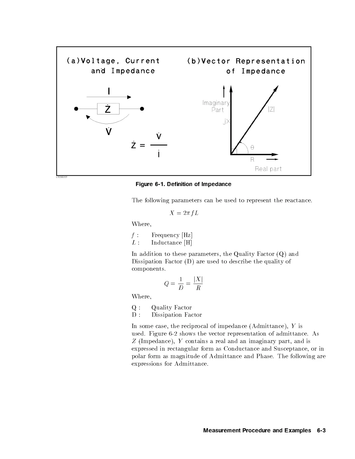
Figure 6-1. Definition of Impedance
The following parameters can be used to represent the reactance.
X
=2
f L
Where,
f
: Frequency [Hz]
L
: Inductance [H]
In addition to these parameters, the QualityFactor (Q) and
Dissipation Factor (D) are used to describe the quality of
components.
Q
=
1
D
=
j
X
j
R
Where,
Q: QualityFactor
D: Dissipation Factor
In some case, the recipro cal of imp edance (Admittance),
Y
is
used. Figure 6-2 shows the vector representation of admittance. As
Z
(Impedance),
Y
contains a real and an imaginary part, and is
expressed in rectangular form as Conductance and Susceptance, or in
polar form as magnitude of Admittance and Phase. The following are
expressions for Admittance.
Measurement Procedure and Examples 6-3


 To Next Page