Procedure:
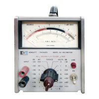
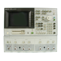
1. Connect the equipment as shown in Figure 10-4.
Note
if the Interface Box is not available, use the following cables and
adapters as a substitute. Figure 10-5 shows the test setup without
the interface box. The center conductors of H
CUR
and H
POT
are
connected to the Hi-input of the multimeter. The center conductors
of the L
CUR
and L
POT
are connected to Lo-input of the multimeter.
Cable BNC(m)-to-BNC(m) 30 cm HP PN 8120-1838 2 ea.
Test Lead 2 BNCs(m) to HP PN 8120-1661
3 alligator clips
Tee, BNC(m)(f )(f ) Adapter HP PN 1250-0781 2 ea.
2. Set the multimeter to DCV.
3. Perform a SYSTEM RESET as describ ed in \System Reset".
4. Set HP 4284A's controls as follo ws:
Test Signal level: 0 mV
High Power Option: OFF
DC Bias: ON
Note
The High Power Mo de cannot be changed when the DC Bias is set to
ON.
Set the DC Bias voltage in accordance with Table 10-5, and
conrm that the Multimeter readings are within the test limits
given in Table 10-5.
Table 10-5. DC Bias Level Test Limits (Hi-PW OFF)
Bias Level Test Limits
1.5 V 1.425 V to 1.575 V
2V 1.9 V to 2.1 V
Note
Steps 6 through 7 should b e p erformed only when the HP 4284A is
equipped with Option 001.
5. set the HP 4284A's controls as follows:
Test Signal Level: 0 mV
High Power Option: ON
DC Bias: ON
6. Set the DC Bias Level in accordance with Table 10-6, and conrm
that the Multimeter readings are within the test limits given in
Table 10-6 .
10-10 Performance Tests


 To Next Page