4-25 In the variable tracking ratio mode, the tracking
ratio control connects a fixed resistor in parallel with
the upper part and a rheostat (the variable tracking ratio
control) in parallel with the lower part of the voltage
divider that forms the -20-volt reference. Turning the
control counter- clockwise reduces the resistance of the
rheostat and lowers the voltage of the negative output.
4-27 Except for differing component designations and
values, paragraphs 4-15 through 4-18,4-20, and 4-21,
which describe the voltage comparison amplifier, OR-gate,
driver, series regulator, turn-on control, and circuit
protection components of the +20-volt regulator circuit,
also apply to the +6-volt regulator. The only difference in
circuit operation lies in the control of the current
comparison amplifier, and thus the type of current limit the
supply has.
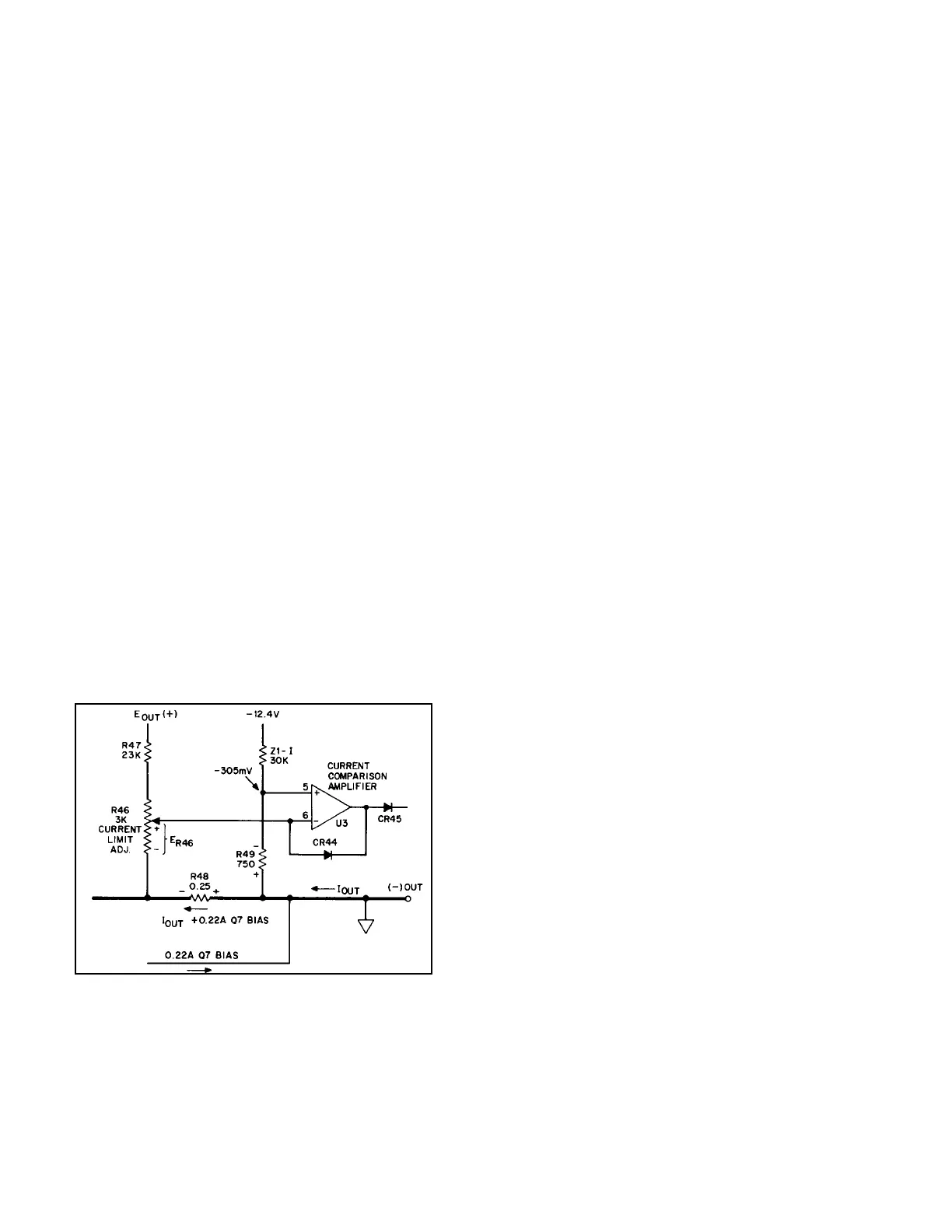
4-28 Current Foldback Circuit. (For this discussion
refer to the Figure 7-1 schematic and to Figure 4-1.) The
differential input signal to the current comparison amplifier
is the algebraic sum of three circuit voltages:
1.The voltage across R49. E
R49
remains constant at
-305mV.
2. The voltage across the lower part of R46 (see
Figure 4-1). E
R49
is proportional to the regulator
output voltage and equals 440mV when the
supply output is 6 volts.
3. The voltage across current monitoring resistor
R48. E
R48
is proportional to the sum of the
regulator output current and the 0.22A bias
current that flows through R54 and R48.
Figure 4-1. Foldback Current Limit Circuit in 6V Supply
4-29 When the supply's output current is below the cur-
rent limit that corresponds to its output terminal voltage
(see Figure 3-3), the inverting input (U3-6) of the current
comparison amplifier is more positive than its non-inverting
input (U3-5), which is held at -305mV. The negative am-
plifier output that results is clamped by CR44 and reverse
biases OR-gate diode CR45, leaving the voltage comparison
amplifier in control of the supply's output. If the load resis-
tance is decreased, the higher output current increases
E
R48
until the algebraic sum of E
R48
and E
R46
makes the
current comparison amplifier's inverting input slightly more
negative than the -305mV potential on its non-inverting in-
put. When this happens, the output of this amplifier goes
positive and forward
biases CR45. Since the current through
CR45 tends to reduce the output of the supply, the output
of the voltage comparison amplifier goes negative in oppo-
sition to this change and reverse biases CR46 to leave the
current comparison amplifier in control of the output. Now
that the current comparison amplifier is in control and for as
long as the overload remains, the supply's output voltage
and current vary so as to maintain this amplifier's differen-
tial input signal near zero volts. This results in the output
current limit characteristics shown in Figure 3-3.
4-30 If we assume for example that the voltage control
is set for 5 volts and the load resistance is slowly
decreased, the supply goes into current limit at about
2.47 amps. Here is why it occurs at that value. At a 5-
volt supply output, E
R46
is 5/6 of 440mV, or 367mV. In
order for the algebraic sum of E
R46
and E
R48
to go as far
negative as -305mV and drive the amplifier output
positive, E
R48
must reach -672mV. Once E
R48
reaches
this value, the current comparison amplifier controls the
series regulator transistor so as to prevent E
R48
(and thus
the supply's output current) from increasing further. At
0.25 ohms, R48 develops -672mV at 2.69 amps. Since
0.22 amps of the current through R48 is bias current for
Q7, the nominal current limit corresponding to a 5-volt
output is 2.69 amps minus 0.22 amps, or about 2.47
4-31 If the load resistance continues to decrease, it pulls
the output voltage lower. This reduces E
R46
until at a zero
output voltage E
R46
becomes zero, leaving E
R48
equal in
magnitude to E
R49
This -305mV drop across R48 corre-
sponds to a 1.22-amp current through R48 and a 1-amp
shortcircuit current at the output of the supply.
4-32 In the +6-volt regulator, as in the +20-volt
regulator, the turn-on bias current for the series regulator
transistor is switched on and off by Q15 in the turn-on
control circuit to prevent output voltage transients.
4-3
4-33 0 To +18-Volt Regulator (Model 6237B)
4-34 Except for differing component designations and
4-26 0 To +6-Volt Regulator (Model 6236B)